EasyManua.ls Logo

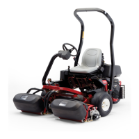
Toro GREENSMASTER 3100 Service Manual

Toro GREENSMASTER 3100
234 pages
To Next Page IconTo Next Page
Page #1 background imageLoading...
Page #1 background image
Service Manual
Greensmaster
®
3100/3050
Preface
This publication provides the service technician with
information for troubleshooting, testing, and repair of
major systems and components on the
Greensmaster 3100 and 3050.
REFER TO THE TRACTION UNIT, CUTTING UNIT
AND ACCESSORY OPERATOR’S MANUALS FOR
OPERATING, MAINTENANCE AND ADJUSTMENT
INSTRUCTIONS. Space is provided at the end
of Chapter 2 in this publication to insert the Operator’s
Manuals and Parts Catalogs for your machine. Replace-
ment Operator’s Manuals are available by sending com-
plete Model and Serial Number of traction unit and
cutting unit to:
The Toro Company
8111 Lyndale Avenue South
Minneapolis, MN 55420
The Toro Company reserves the right to change product
specifications or this publication without notice.
This safety symbol means DANGER, WARN-
ING, or CAUTION, PERSONAL SAFETY IN-
STRUCTION. When you see this symbol,
carefully read the instructions that follow.
Failure to obey the instructions may result in
personal injury.
NOTE: A NOTE will give general information about the
correct operation, maintenance, service, testing or re-
pair of the machine.
IMPORTANT: The IMPORTANT notice will give im-
portant instructions which must be followed to pre-
vent damage to systems or components on the
machine.
© The Toro Company - 1991, 1998, 2002, 2004, 2005
Part No. 92784SL, Rev. E
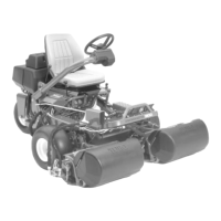
Table of Contents

Other manuals for Toro GREENSMASTER 3100

Questions and Answers:

Toro GREENSMASTER 3100 Specifications

General IconGeneral
Cutting Units3
Blade TypeReel
Drive SystemHydrostatic
Horsepower21.5 hp (16 kW)
Engine Power21.5 hp (16 kW)
Number of Blades11

Summary

Chapter 1 - Safety

Safety Instructions

General safety guidelines and warnings for operating the Greensmaster 3100.

Maintenance and Repair Safety

Safety precautions for service, maintenance, and repair procedures.

Chapter 4 - Hydraulic System

Hydraulic Flow Diagrams

Visual representations of hydraulic oil flow for various machine operations.

Hydraulic Schematic

Detailed schematic illustrating the hydraulic system components and connections.

Hydraulic System Troubleshooting

Guides for diagnosing and resolving hydraulic system issues.

Hydraulic System Testing Procedures

Methods for testing hydraulic components using specialized equipment.

Hydraulic System Repairs

Instructions for removing, installing, and repairing hydraulic components.

Chapter 5 - Electrical System

Electrical System Wiring Schematic

Diagrams illustrating electrical connections for different machine serial number ranges.

Electrical System Troubleshooting

Guides for diagnosing and correcting electrical system malfunctions.

Electrical System Testing

Procedures for testing electrical components like switches and meters.

Electrical System Repairs

Instructions for adjusting and replacing electrical switches and components.

Chapter 7 - 4 Bolt Adjust Cutting Units

4 Bolt Adjust Cutting Units Troubleshooting

Factors affecting cut quality and their possible solutions.

4 Bolt Adjust Cutting Units Set Up and Adjustments

Procedures for adjusting reel contact, bedknife, height of cut, and rollers.

Chapter 8 - Single Point Adjust Cutting Units

Single Point Adjust Cutting Units Troubleshooting

Factors affecting cut quality and their possible solutions.

Chapter 9 - Grooming Reel Cutting Units

Chapter 10 - Dual Point Adjust Cutting Units

Related product manuals