Do you have a question about the Toro Greensmaster TriFlex 3320/3420 and is the answer not in the manual?
General safety instructions for operating, transporting, maintenance, and storage of the machine.
Instructions for safely lifting the machine using jacks and supports.
Information on safety and instruction decals affixed to the machine.
Instructions to insert Operator's Manuals and Parts Catalogs for the machine and optional equipment.
Information on maintenance procedures and recommended service intervals for the machine.
Tables for decimal/millimeter equivalents and US to metric conversions.
Recommended fastener torque values for various applications and fastener types.
Specifications for the Briggs & Stratton Vanguard V-Twin OHV engine.
Information on engine specifications, maintenance, troubleshooting, testing, and repair.
Procedures for adjusting choke and throttle cables for proper engine operation.
Procedures for servicing and repairing the fuel evaporative control system and fuel tank.
Specifications for the Kubota water-cooled Diesel engine, Model D902-E3B.
Information on engine specifications, maintenance, troubleshooting, testing, and repair.
Procedure to adjust the throttle control for proper engine operation.
Procedures for servicing and repairing the air cleaner assembly, exhaust system, fuel tank, radiator, and starter motor.
Specifications for hydraulic components including pumps, motors, valves, and reservoir.
Information on operator's manuals, fluid levels, pushing the traction unit, and relieving system pressure.
Diagram illustrating the hydraulic system layout and component connections.
Diagrams showing oil flow for traction circuit, lower cutting units, raise cutting units, and turns.
List of special tools required for hydraulic system testing and service.
Charts to help diagnose general hydraulic, traction, lift/lower, and steering circuit problems.
Procedures for testing hydraulic system components like relief valves, pumps, and motors.
Procedures for adjusting manifold relief valves and traction control assembly.
Precautions and procedures for removing/installing hydraulic components and flushing the system.
Information on operator's manuals, TEC controller, CAN-bus communications, and electrical drawings.
Overview of the 12 Volt DC and 48 Volt DC electrical systems on the machine.
Explanation of the Turf Guardian™ Leak Detector System operation and leak alert.
List of special tools including multimeter, diagnostic display, and protectors.
Information on diagnostic lights, fault codes, starting problems, and general operational issues.
Procedures for quick checks of the 12 Volt battery, engine charging system, and glow plug system.
Procedures for adjusting parking brake switch, and neutral and mow switches.
Procedures for testing ignition switch, engine oil pressure light, and indicator lights.
Identification and function of fuses in the fuse block for the Greensmaster 3320.
Identification and function of fuses in the fuse block for the Greensmaster 3420 (below SN 312000000).
Identification and function of fuses in the fuse block for the Greensmaster 3420 (above SN 312000000).
Identification and function of fuses for the electric reel drive system.
Information on fusible links for circuit protection and testing procedures.
Procedure for testing and replacing the hour meter.
Testing procedures for the operator presence seat switch.
Testing procedures for the neutral and mow proximity switches on the console.
Testing procedures for the parking brake proximity switch.
Testing procedures for the joystick raise and lower switches.
Testing procedures for the backlap switch used to control reel backlap.
Testing procedures for the electric reel contactor that connects generator, motors, and battery pack.
Testing procedures for the reel speed potentiometer.
Information on the TEC controller, its inputs, outputs, and diagnostic capabilities.
Testing procedures for solenoid valve coils used in hydraulic system control.
Information on various relays and testing procedures.
Testing procedures for kill and start relays used on the machine.
Information on CAN-bus termination resistors and testing.
Information on the protection diode for the electric reel circuit and testing.
Testing procedures for the location ID module used in the electric cutting reels circuit.
Testing procedures for the starter solenoid on Greensmaster 3320.
Procedure for testing the fuel pump capacity on Greensmaster 3420.
Information on the fuel solenoid's operation and testing on Greensmaster 3420.
Procedure for testing the temperature sender on Greensmaster 3420.
Information on the diode assembly and testing procedures.
Testing procedures for the oil level sensor in the leak detector system.
Testing procedures for the leak detector alarm.
Specifications for tire pressure, wheel lug nut torque, and wheel motor/hub lock nut torque.
Information on operator's manuals and opening electrical circuit to cutting units.
List of special tools including wheel hub puller and grease fitting.
Procedure for adjusting the parking brake.
Procedures for servicing wheels, brake system, and brake cables.
Procedures for removing and installing wheels, including torque specifications.
Procedures for removing and installing brake assembly components.
Diagram and procedures for removing and installing brake cables.
Disassembly and assembly procedures for the rear wheel spindle assembly.
Removal and installation procedures for the rear steering fork assembly.
Diagrams and procedures for disassembling and assembling the control console.
Procedures for raising, removing, and installing the tank mount plate assembly.
Disassembly and assembly procedures for the cutting unit crossarm assembly.
Removal and installation procedures for the cutting unit suspension assembly.
Disassembly and assembly procedures for the cutting unit suspension components.
Illustration of the frame assembly with fastener tightening torque recommendations.
Specifications for frame construction, reel construction, bearings, drive, HOC, bedknife, and roller type.
Information on operator's manuals, supporting cutting units, and opening electrical circuit.
List of special tools for servicing DPA cutting units.
Factors influencing cutting performance, such as tire pressure, engine speed, and reel speed.
Procedures for adjusting bedknife parallel to reel, rear roller shims, and height-of-cut.
Procedures for backlapping, bedbar assembly, bedknife replacement, and reel service.
Procedure for backlapping cutting units to maintain sharp cutting edges.
Disassembly and assembly procedures for the bedbar assembly.
Procedures for disassembling and assembling the bedbar adjuster.
Procedures for replacing and grinding the bedknife.
Procedures for removing and installing the cutting reel assembly.
Steps for removing the cutting reel assembly from the cutting unit.
Steps for installing the cutting reel assembly into the cutting unit.
Disassembly, inspection, and assembly procedures for the cutting reel.
Instructions on preparing the reel for grinding according to specifications.
Procedures for removing and installing the reel motor adapter.
Procedures for removing and installing the front roller.
Procedures for removing and installing the rear roller.
Procedures for disassembling and assembling roller components.
Information on installing the optional rear roller brush kit.
Specifications for groomer mounting, reel construction, drive, HOC, and brush.
Information on installation, operation, maintenance, and opening electrical circuit.
Factors affecting grooming performance and mechanical problems with the grooming reel.
Variables influencing grooming performance, such as turf conditions and management programs.
Common mechanical problems with the grooming reel and their possible causes and corrections.
Procedures for adjusting groomer height/depth.
Procedure for adjusting the groomer reel height above the soil level.
Procedures for groomer belt replacement, cover service, reel service, and idler assembly.
Procedure for replacing the groomer drive belt on forward rotating groomer drive.
Procedures for removing and installing the groomer cover assembly.
Procedures for removing and installing the grooming reel on forward rotating groomer drive.
Procedures for removing and installing the grooming reel on counter rotating groomer drive.
Procedures for disassembling, inspecting, and assembling the grooming reel.
Procedures for replacing grooming reel bearings and seals.
Procedures for removing and installing the idler assembly.
Procedures for disassembling and assembling the idler assembly.
Disassembly and assembly procedures for the lift arm assembly.
Procedures for removing and installing the groomer brush.
Diagram of the complete hydraulic system showing component connections and flow paths.
Electrical schematics for Greensmaster 3320 and 3420 models based on serial numbers.
Diagrams illustrating the wire harness layout for Greensmaster 3320/3420 models based on serial numbers and E-Reels.
| Brand | Toro |
|---|---|
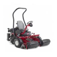
| Model | Greensmaster TriFlex 3320/3420 |
| Category | Lawn Mower |
| Language | English |