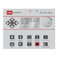
Controller Components................................................. 2
Selecting Control Options ............................................ 3
Before Programming the Controller…..........................4
About The Controller’s Memory................................... 4
Set Satellite Operating Mode........................................ 4
Set Current Time and Day............................................. 5
Set Station Run Times................................................... 5
Set Program Start Time(s) ............................................ 6
Set Active Day Watering Schedules ............................ 7
• Calendar Schedule.................................................... 7
• Interval Schedule ...................................................... 8
Set Program Repeat and Soak ..................................... 9
Program Operation Pause and Cancel ...................... 10
Manual Control Operations ...................................10- 12
Cycle Mode................................................................... 10
Syringe Mode ............................................................... 11
Multi-Manual Mode ...................................................... 12
Set Satellite Address................................................... 13
Set Percent Adjust....................................................... 13
Reviewing Program Information ................................ 14
Special Functions................................................... 14-15
Self Test........................................................................ 14
Initialization.................................................................. 14
Radio Calibration Test................................................. 15
Link Monitor ................................................................ 15
Troubleshooting .......................................................... 16
Lithium Battery Installation (Optional)....................... 16
Manual Output Switch Operation............................... 17
Power Indicator Lamps ............................................... 17
Program Data Reference Form....................................18
1
Table of Contents
Power Specifications
Line Voltage: 115/230 V a.c. 50/60 Hz (switchable),
130 VA (100W)
Current Draw (no load): 0.21A @ 115 V a.c., 60 Hz, 0.10A
@ 230V, 50 Hz
Current Draw (maximum load): 0.90A @ 115 V a.c, 60 Hz,
0.42A @ 230 V a.c, 50 Hz
Secondary Voltage Output: 24 V a.c., 3.2A (77 VA)
Maximum Load Per Station Output: 0.75A (18 VA)
Maximum Load Per Pump/Master Valve Output:
0.75A (18 VA)
Hardware Features
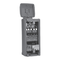
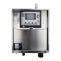
Plastic or Painted Stainless Steel Cabinetry
Front, Back and Top Locking Covers
Removable Station Output and Common/Pump Modules
Modular Station Output:
16 to 64 stations in 8-station increments
Fuses and Circuit Breakers
Power Supply:
1.5A On/Off Switch/Circuit Breaker – Main Power Input
3.2A Fuse (Slow-Blow) – Field Output
4A Circuit Breaker – Control Functions
Communication Modem (optional): 3/4A (Fast-Blow)
Pump/Common & Communication Surge Protection
Module (optional): 1/2A (Fast-Blow)
Electromagnetic Compatibility
Domestic: This equipment has been tested and found to
comply with the limits for a FCC Class A digital device,
pursuant to part 15 of the FCC Rules. These limits are
designed to provide reasonable protection against harmful
interference when the equipment is operated in a
commercial environment. The equipment generates, uses,
and can radiate radio frequency energy and, if not
installed and used in accordance with the instruction
manual, may cause harmful interference to the radio
communications. Operation in a residential area is likely to
cause harmful interference in which case the user will be
required to correct the interference at his own expense.
International: This is a CISPR 22 Class A product. In a
domestic environment, this product may cause radio
interference, in which case the user may be required to
take adequate measures.