Installation
CAUTION
BeforeattemptingtoinstalltheProPass-11
HPHydraulicPowerPack,ensurethat:
•TheProPassislocatedonrmlevel
ground.
•TheProPassjackstandislowered.
•Allexternalhydraulicandelectricalpower
sourcesaredisconnected.
•TheProPassshouldbepreventedfrom
unexpectedmovementbyblockingthe
wheelsatthefrontandtherear.
•UseanassistantwhenliftingthePower
Packassembly.
1.FollowingtheinstructionsgivenintheOperator’s
Manualforthemachine.RemovetheTwin
Spinneroptionandsecurethehydraulicpower
andreturnhoses.
Note:ProPassmodelsmanufacturedafterApril
2005featureapre-drilledchassisrearwall.If
yourProPassispre-drilledskipinstructions
2-13.
2.CheckthattheProPasschassisrearwallis
cleartomountthehydraulictank.
Note:Twomountingboltsmustberemoved
fromthechassisrearwalltoallowthehydraulic
tanktobemounted.Usetheboltsformounting
thetank.
3.Removethehydraulictankassemblyfromthe
crate.
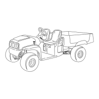
4.Supportthehydraulictankfromunderneathand
positionthetankagainsttheProPasschassis
rearwall.Thetankshouldbecenteredevenly
fromlefttorightandshouldbepositioned
vertically(Figure1).
g013856
Figure1
1.Hydraulictank
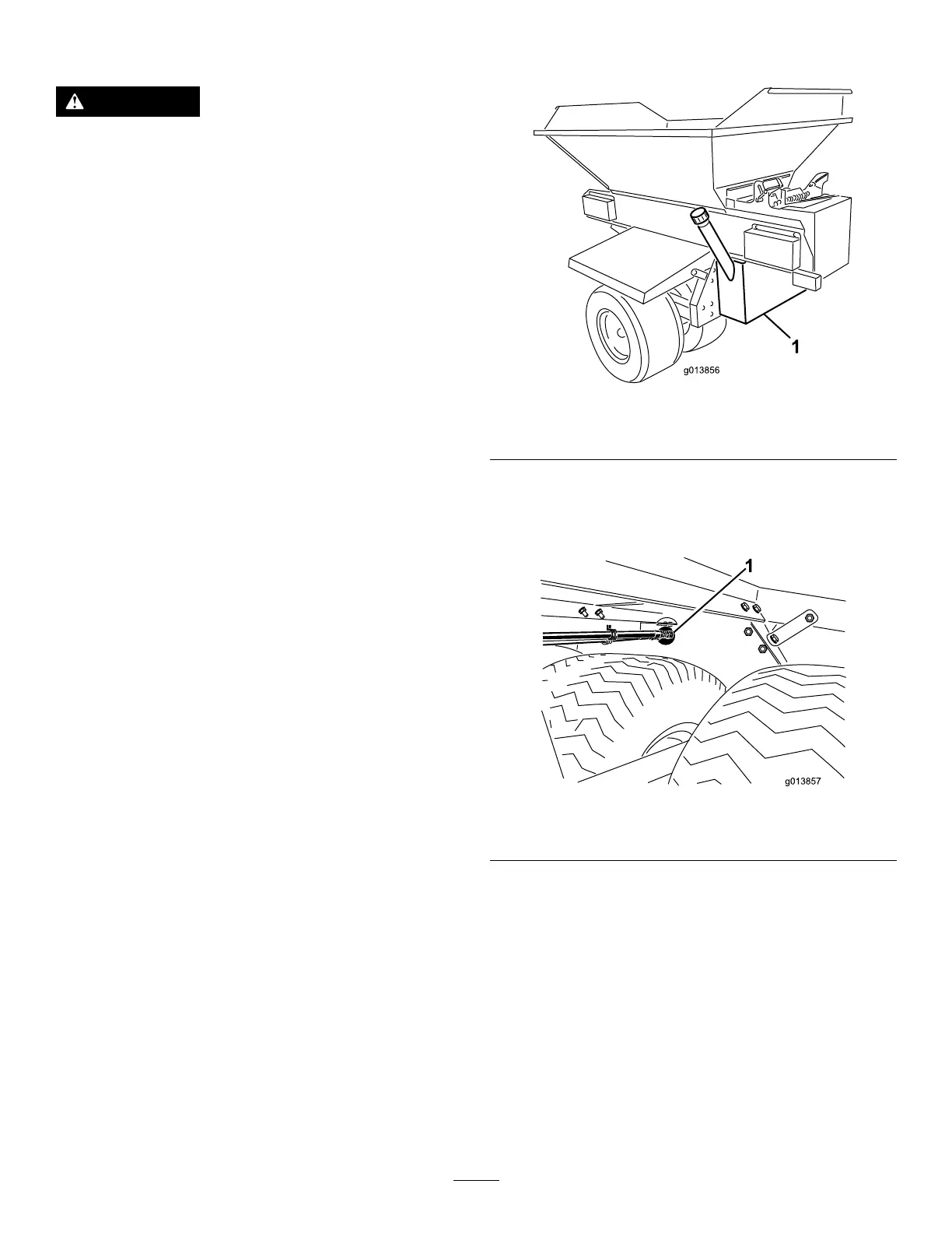
5.Ensurethattheinletandoutletttingsandthe
hoseguidemountingbracketalltcleanlywithin
theroundholesintheProPasschassisrearwall
(Figure2).
g013857
Figure2
1.Holesinthechassis
6.Ensurethatthehydraulictankislevel.
7.UsingC-clamps,orsimilardevices,temporarily
clampthehydraulictankrmlyinplaceonthe
ProPasschassisrearwall.
8.Recheckthatthehydraulictankislevel.
9.Markthepositionofthehydraulictankmounting
holesontotheProPasschassisrearwall.
10.Un-clampandremovethehydraulictank.
11.Centerpunchthepositionofthemarkedholes.
12.Drilla7/16inchdiameterholethroughthe
ProPasschassisrearwallineachmarkedand
punchedposition.
3

 Loading...