Machineswith127cm(50-inch)
MowerDecks
1.Parkthemachineonalevelsurface,disengage
theblade-controlswitch,andmovethe
motion-controlleversoutwardtothePARK
position.
2.Shutofftheengine,removethekey,andwait
forallmovingpartstostopbeforeleavingthe
operatingposition.
3.Removethemowerdeck;refertoRemovingthe
MowerDeck(page49).
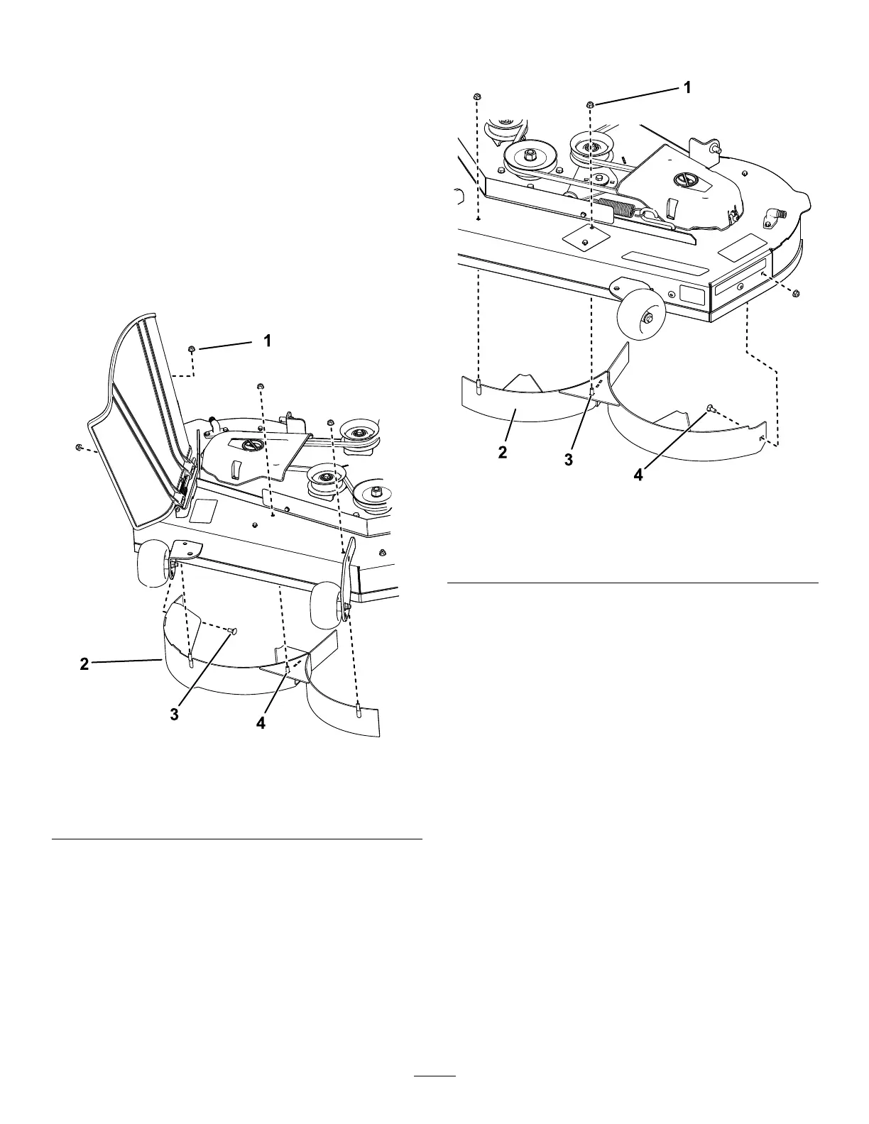
4.Removethe3locknuts(5/16inch)fromthe
weldedpostsoftherightbafe(Figure13).
g297022
Figure13
1.Locknut—5/16inch(4)3.Carriagebolt—5/16x3/4
inch
2.Rightbafe4.Weldedpost(3)
5.Removethe2carriageboltsand2locknuts
securingtherightbafetothedeckandremove
thebafe(Figure13).
6.Locatethe3boltsinloosepartsandusethe
existinglocknutsandinstallthesefastenersinto
theholesusedfortheweldedposts(Figure13)
topreventyingdebris.
Note:Installtheboltupward,throughthe
undersideofthedeckanduseanexisting
locknuttosecurefromthetopside.
7.Removethe2locknuts(5/16inch)fromthe
weldedpostsoftheleftbafe(Figure14).
g297021
Figure14
1.Locknut—5/16inch(3)3.Weldedpost(2)
2.Leftbafe4.Carriagebolt—5/16x3/4
inch
8.Removethecarriageboltandlocknutsecuring
theleftbafetothedeckandremovethebafe
(Figure14).
9.Locatethe2boltsinloosepartsandusethe
existinglocknutsandinstallthesefastenersinto
theholesshowninFigure14onthemowerdeck
topreventyingdebris.
Note:Installtheboltupward,throughthe
undersideofthedeckanduseanexisting
locknuttosecurefromthetopside.
10.Removethenutfromthegrassdeectorrod
underthemowerdeck(Figure15).
17
 Loading...