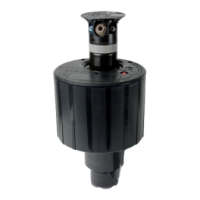
CAUTION
Do not apply pressure directly on center shaft of drive assembly. Push on outer edge of drive assem-
bly housing. Excessive force applied directly to shaft may cause permanent damage to drive assem-
bly and loss of sprinkler performance.
Lawn and Hi-Pop Sprinkler Reassembly
1. Invert riser, install drive assembly (threaded end first) and variable stator assembly.
NOTE: To aid installation of variable stator assembly in Hi-Pop models, mark a piece of
3
⁄4" PVC pipe to 10
3
⁄4" from one end.
Place stator assembly over end of pipe and insert into riser until stop is felt or 10
3
⁄4"mark is even with riser bottom.
2. Place return spring, riser seal and cap on riser, compressing spring with cap.
NOTE: Inspect Arc Disc seal for damage and replace if necessary.
3. Grasp riser firmly between cap and riser top and install Arc Disc seal, tapered side up (See Figure 8.)
4. Install Arc Disc, aligning center of part circle spray pattern with designated riser tab. (See
Figure 9.)
NOTE: Lawn Pop-up has only one riser tab for alignment of Arc Disc.
5. Screw nozzle assembly into drive assembly (do not overtighten) and slowly release cap.
6. Insert basket screen into riser bottom (Hi-pop). Press screen (Lawn Pop-up) onto riser bottom, aligning keys of screen
with keyways of riser bottom.
7. Insert riser into body (see
NOTE below).
NOTE: To properly align part-circle models, insert riser assembly into body aligning marked riser keyway with marked
body key. These marks are located on bottom of riser (under screen on Lawn Pop-up) and raised dot on body exterior.
8. Screw cap onto body.
9. Tighten locking cap set screw (Hi-Pop only).
4
Figure 7
Figure 8 Figure 9
RISER
(Lawn Pop-Up shown)
DRIVE ASSEMBLY
FLAT BLADE
SCREWDRIVER
DO NOT PRESS
HERE
ARC DISK
SEAL
ARC DISK
TAPERED
AREA
RISER
RISER
CENTER OF
SPRAY
PATTERN
USE THIS RISER
TAB FOR SPRAY
ALIGNMENT
RISER TAB
ARC DISC
SEAL
TOP VIEW
 Loading...