5
4400 Series UPS Seismic Kit Installation Instructions – 94016-002
2 4400 50kVA Seismic Installation
Table 2 lists the contents of the 4400 50kVA (4400500SEISMICKIT). Figure 2.1 shows the order of
assembly for the [bolt + lockwasher + washer] fastener group.
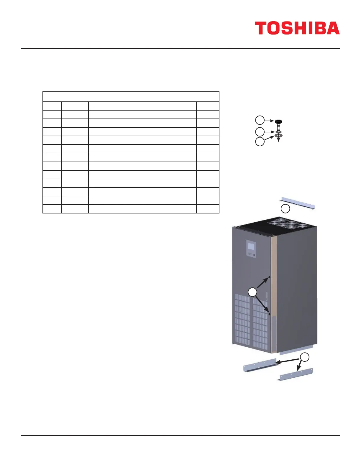
TABLE 2 50 KVA SEISMIC KIT CONTENTS
440500SEISMICKIT Contents
No. P/N* Description Quan
5 66437 TOP SEISMIC BRACKET 1
6 67193 SEISMIC MOUNTING CHANNEL 2
7-a – Hex Bolt, 1/4—20,1-1/2” 1
7-b – Flat Washer, 1/4 1
7-c – E—Ring, F/0.25 Shaft 1
10-a – Hex Bolt, 1/2—13 x 3/4” 8
10-b – Lock Washer, 1/2 8
10-c – Flat Washer, 1/2 8
11-a – Hex Bolt, 5/16—18 x 1” 4
11-b – Lock Washer, 5/16 4
11-c – Flat Washer, 5/16 4
– 94016 4400 Seismic Kit Installation Manual 1
1. Prepare the oor anchorages. Arrange the anchorages to ac-
commodate the nal layout including placement for ancillary
battery and/or Auxiliary cabinets. (Figure 2.3)
2. Prepare the wall anchorages. Key measurements o the an-
chorage placement in Step 1. (Figure 2.4)
3. Table 2 lists the components of the 50kVA Seismic Kit. Figure
2.2 shows the Seismic anchorage components in the Seismic Kit
for the 50kVA cabinets.
4. Assemble the fastener groups in Table 2, [7a-7c], [10a-10c], and
[11a-11c] as shown in Figure 2.1.
5. Secure the Top Seismic Bracket [5] to the top rear of the UPS
using three (3) fastener group [11]. (Figure 2.5)
6. Position the UPS over the oor anchors
7. Slip each Seismic Mounting Channel [6] over the three oor
anchors on each side of the UPS.
8. Tilt the Base bracket up against the UPS bottom bracket on the
UPS base.
9. Align the holes in the Seismic Mounting Channels [6] with the
UPS bottom brackets.
10. Use the remaining eight (8) fastener group [11] to secure the
Seismic Mounting Channels [6] to the UPS bottom brackets.
(Figure 2.6, Figure 2.7)
11. Secure the Top Seismic Bracket to the wall anchors using 5/16” Bolts.
12. Once installation is complete, secure the door of the UPS using the two
(2) Fastener Group [7]. (Figure 2.8)
a
b
c
FIGURE 2.1: FASTENER
GROUP (BOLT +LOCK
WASHER + WASHER)
P/N 440500SEISMICKIT
5
6
7
5
FIGURE 2.2: SEISMIC KIT
COMPONENTS (50 KVA)
 Loading...