51
14-5.Facing test
14-6.RS-485 communication check
14-7.Checking on RS-485 send and receive circuit of the
controller and interface
No. Check point
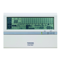
1 At both sides of the controller and handy remote controller, perform setting and display check.
2 Before starting the check, discuss and determine the air conditioners checking order and procedure.
3
Check 1:
Check that the unit name and operation state match between the controller and the handy remote controller.
4
Check 2:
Check that the setting operation from the controller can change the setting in the handy remote controller.
5
Check 3:
Check that returning the setting to the previous state in the handy remote controller can change the setting in the controller.
6 Proceed to the next air conditioner with check.
No. Check point
1 At both the Digital Input / Output Relay Interface and the Energy Monitoring Relay Interface, check that the POWER LED1 (Red)
is lit and the RS-485 LED2 (Green) is blinking.
2 Check that the wiring is connected to the RS-485 terminal block of the controller.
3
Check that the wiring is connected to the RS-485 terminal blocks of the Digital Input / Output Relay Interface and the Energy
Monitoring Relay Interface.
4 Check that the wiring polarity (+), (-) is correct.
5
Check that the address and switch are correctly set for the Digital Input / Output Relay Interface and the Energy Monitoring Relay
Interface.
6
Check that the settings in the “System equipment configuration” and “Address Setting” sheets in the setting file match the address
setting of the Digital Input / Output Relay Interface or the Energy Monitoring Relay Interface.
No. Check point
1 Check that the RS-485 LED2 (Green) of the interface is blinking.
Error message
× NG1:
The POWER LED1 (Red) is off.
Check if the Digital Input / Output Relay Interface or the Energy
Monitoring Relay Interface is turned on.
× NG2:
The RS-485 LED2 (Green) is off.
Check the RS-485 wiring as shown in the step (2) and the subsequent
steps below.
{ OK:
The RS-485 LED2 (Green) is blinking.
When the LED2 (Green) is blinking, if S06:BMS-IFWH communication
error or S07:BMS-IFDD communication error occurs, perform (6)
shown below.
Error message
{ OK:
The RS-485 send circuit of the controller is normal.
The RS-485 receive circuit of the interface is normal.
 Loading...