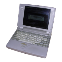
Do you have a question about the Toshiba T3100e and is the answer not in the manual?
Check if the power indicator lights up correctly.
Verify the integrity and connection of power supply unit connectors.
Measure output voltages of the power supply using a multimeter.
Replace the power supply unit if other checks fail.
Analyze error messages displayed on the screen for system board issues.
Check system status using the printer port LED codes.
Run diagnostic tests to identify system board failures.
Replace the system board if diagnostic tests indicate failure.
Verify if the diagnostics program loads correctly from the FDD.
Analyze messages displayed during FDD diagnostics for errors.
Clean the FDD heads using a cleaning disk.
Run the floppy disk drive diagnostic test.
Inspect the FDD connection to the system board.
Install and connect a new FDD to test functionality.
Check the status of the HDD activity indicator light.
Analyze error messages related to HDD operation.
Execute the hard disk formatting procedure.
Run the hard disk drive diagnostic test.
Verify the HDD signal and power cable connections.
Check the HDD jumper strap settings for correct configuration.
Install and connect a new HDD to test functionality.
Test keyboard input by typing characters and observing screen output.
Run the keyboard diagnostic test using a diagnostics disk.
Check the keyboard cable connection to the system board.
Connect a new keyboard to test functionality.
Perform an initial check of the plasma display for basic functionality.
Run the display diagnostic test to identify issues.
Inspect the plasma display panel (PDP) cable connections.
Connect a new plasma display unit to test functionality.
Details subtests for system hardware checks, including ROM checksum.
Details subtests for RAM, including constant data and address patterns.
Details subtests for keyboard functionality, like pressed key display.
Details subtests for display functionality, including VRAM and graphics modes.
Details subtests for FDD read/write operations and address checks.
Details subtests for printer functionality, including ripple pattern and function tests.
Details subtests for asynchronous communication port testing.
Details subtests for HDD read/write, address uniqueness, and pattern tests.
Details subtests for real-time clock and backup memory checks.
Details subtests for Numeric Data Processor (NDP) functionality.
Details subtests for expansion unit functionality.
Performs ROM checksum test on the system board.
Reads and displays the system hardware status bits.
Displays pressed keys on screen, checking character display.
Displays scan code, character code, and keytop for pressed keys.
Writes and reads data to video RAM to check its integrity.
Checks character attributes like normal, intensified, reverse, blinking.
Displays the character set in 40x25 mode.
Displays character string shifting in 80x25 mode.
Displays color sets in 320x200 graphics mode.
Displays color blocks in 640x200 graphics mode.
Displays color blocks in 640x400 graphics mode.
Confirms pages can be changed in 40x25 mode.
Displays 'H' characters on the entire screen.
Tests LED status and font change functionality.
Performs CRC check with continuous read operation of floppy disk tracks.
Writes data to all tracks, reads it back, and compares with original data.
Writes random data to random addresses and compares with original data.
Writes specified data to a specified address, track, and head.
Reads data from a specified address, track, and head.
Prints characters with shifting one character to the right.
Prints various print types like normal, double width, compressed.
Checks data, control, and status lines using a wraparound connector.
Performs data send/receive test using RS-232-C wraparound connector.
Tests communication between two machines using RS-232-C direct cable.
Sends data and checks if it's returned correctly.
Receives data and checks if it matches sent data.
Checks data sent from modem card to RS-232-C line via loopback.
Checks data transmission through a telephone line via PBX.
Sends pulse and tone dial automatically to test dialer function.
Generates and checks interrupt request levels.
Performs forward and reverse reading of contents from tracks.
Writes different sector data at each track and compares it.
Writes random data to random addresses and compares with original data.
Writes pattern data to cylinders and reads while shifting.
Writes and reads pattern data to CE cylinder and compares.
Writes specified data to a specified cylinder and head.
Reads data written to a specified cylinder and head.
Checks ECC circuit functions for a specified cylinder and head.
Writes specified data of two bytes to all cylinders.
Writes specified data to cylinder/head, reads and compares.
Allows inputting new date and time, and checks current settings.
Writes and reads data to backup memory, comparing the results.
Checks if the real-time clock correctly increments time values.
Checks NDP control word, status word, bus, and arithmetic functions.
Tests 8-bit bus wrap around functionality (requires special tool).
Writes and reads data to monochrome display memory.
Tests 16-bit bus wrap around functionality (requires special tool).
Describes physical formatting, including all track, good track, bad track formats.
Details the steps and options for performing hard disk formatting.
Explains the program that moves HDD heads to safe areas for data protection.
Details the steps to execute the HDD seek to landing zone program.
Explains head loading and seek/read operations for FDD head cleaning.
Details the steps for performing FDD head cleaning using a kit.
Logs error information generated during tests, storing it in RAM.
Describes how to manipulate and save error log information.
Automatically runs system, memory, display, FDD, printer, async, HDD, real timer tests.
Details the steps to initiate and control the automated diagnostic tests.
Programs for formatting, copying, and displaying dump lists for FDD/HDD.
Details how to access and use the FDD formatting, copy, and dump functions.
Displays system configuration like BIOS version, memory, drives, ports.
Details how to access and view the system configuration display.
Explains how to access the system setup screens and navigate options.
Details how to automatically or manually change setup options.
Explains the possible values for each setup option, like Hard Disk Type.
Details the pin assignment for the Lithium battery connector (PJ1).
Details the pin assignment for the Serial B interface connector (PJ2).
Details pin assignments for 40-pin (PJ3) and 60-pin (PJ4) expansion bus connectors.
Details pin assignments for the 8-bit expansion slots PJ5A and PJ5B.
Details pin assignments for HDD power, power supply, and FDD connectors.
Details pin assignments for various interface connectors (Serial A, HDC, PDP/LED, PRT/FDD, Fan, CRT, PDP Sensor).
Details pin assignments for memory board connectors (IS 101A, 101B, 102A, 102B).
Details pin assignments for selector, tenkey, keyboard, speaker connectors, and LED board.
Details pin assignments for T3100 support board system interface connectors (PJ101, PJ102, PJ103, PJ104).
Illustrates the key arrangement for the USA keyboard version.
Illustrates the key arrangement for the UK keyboard version.
Illustrates the key arrangement for the Germany keyboard version.
Illustrates the key arrangement for the France keyboard version.
Illustrates the key arrangement for the Spain keyboard version.
Illustrates the key arrangement for the Italy keyboard version.
Illustrates the key arrangement for the Scandinavian keyboard version.
Illustrates the key arrangement for the Switzerland keyboard version.
Shows the numerical identification for each keycap on the keyboard.
| Category | Desktop |
|---|---|
| Manufacturer | Toshiba |
| Model | T3100e |
| Release Year | 1987 |
| CPU | Intel 80286 |
| Resolution | 640x400 |
| Floppy Drive | 3.5" 1.44 MB |
| Operating System | MS-DOS 3.3 |
| Storage | 20 MB HDD |
| Ports | Serial, Parallel |