Home
Toshiba
Desktop
TECRA 9100 Series
Toshiba TECRA 9100 Series - User Manual
428 pages
Manual
Specs
Ask a question
Save Page as PDF
To Next Page
To Next Page
Loading...
Toshiba Personal Computer
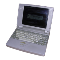
TECRA 9100 Series
Maintenance Manual
TOSHIBA CORPORATION
File Number 960-347
2
Table of Contents
Main Page
Table of Contents
7
Chapter 1 Hardware Overview
11
Table of Contents
14
Default Chapter
15
Features
15
Figure 1-1 Front of the Computer
20
Figure 1-2 System Unit Configuration
21
Figure 1-3 System Unit Block Diagram
22
System Unit Block Diagram
22
Figure 1-4 3.5-Inch FDD (USB External)
29
Inch Floppy Disk Drive (USB External)
29
Table 1-1 3.5-Inch FDD Specifications
29
Figure 1-5 2.5-Inch HDD
30
Inch Hard Disk Drive
30
Table 1-2 2.5-Inch HDD Specifications
30
CD-ROM Drive
31
Figure 1-6 CD-ROM Drive
31
Table 1-3 CD-ROM Drive Specifications
31
DVD-ROM Drive
32
Table 1-4 TEAC DVD-ROM Drive Specifications
33
CD-R/RW Drive
34
Figure 1-8 CD-R/RW Drive
34
Table 1-5 CD-R/RW Drive Specifications
34
COMBO Drive
35
Figure 1-9 COMBO Drive
35
Table 1-6 COMBO Drive Specifications
35
Power Supply
36
Table 1-7 Power Supply Output Rating
37
Batteries
38
Table 1-8 Battery Specifications
38
Table 1-9 Time Required for Quick Charges
39
Table 1-10 RTC Battery Charging/Data Preservation Time
40
Chapter 2 Troubleshooting Procedures
41
Table of Contents
43
Default Chapter
47
Troubleshooting
47
Troubleshooting Flowchart
48
Power Supply Troubleshooting
52
Icons in the LCD Check
52
Procedure 1
52
Error Code Check
53
Procedure 2
53
Procedure 3 Connection Check
59
Procedure 4 Charge Check
60
Procedure 5 Replacement Check
61
System Board Troubleshooting
62
Procedure 1 Message Check
62
Procedure 2 Printer Port LED Check on Boot Mode
65
Procedure 3 Diagnostic Test Program Execution Check
72
Procedure 4 Replacement Check
73
FDD Troubleshooting
74
Procedure 1
74
Procedure 1 FDD Head Cleaning Check
74
Procedure 2 Diagnostic Test Program Execution Check
74
Connector Check and Replacement Check
76
HDD Troubleshooting
77
Procedure 1
77
Procedure 1 Message Check
77
Partition Check
78
Procedure 2
78
Format Check
79
Procedure 4
80
Procedure 4 Diagnostic Test Program Execution Check
80
Connector Check and Replacement Check
81
Keyboard and PAD I/F Troubleshooting
82
Procedure 1
82
Procedure 1 Diagnostic Test Program Execution Check
82
Connector and Replacement Check
83
Display Troubleshooting
85
Procedure 1 Diagnostic Test Program Execution Check
85
Procedure 2 Connector and Cable Check
85
Procedure 3 Replacement Check
85
CD-R/RW Drive Troubleshooting
87
Procedure 1
87
Procedure 1 Diagnostic Test Program Execution Check
87
Connector Check and Replacement Check
88
COMBO Drive Troubleshooting
89
Procedure 1
89
Procedure 1 Diagnostic Test Program Execution Check
89
Connector Check and Replacement Check
90
Modem Troubleshooting
91
Procedure 1
91
Procedure 1 Diagnostic Test Program Execution Check
91
Connector Check and Replacement Check
92
LAN Troubleshooting
93
Procedure 1 Diagnostic Test Program Execution Check
93
Procedure 2 Connector Check and Replacement Check
93
Bluetooth Troubleshooting
94
Procedure 1
94
Procedure 1 Transmitting-Receiving Check
94
Antennas' Connection Check
95
Procedure 3 Antenna Check
96
Procedure 4 Replacement Check
97
Wireless LAN Troubleshooting
98
Procedure 1
98
Procedure 1 Transmitting-Receiving Check
98
Antennas' Connection Check
99
Procedure 3 Antenna Check
100
Procedure 4 Replacement Check
101
Sound Troubleshooting
102
Procedure 1 Diagnostic Test Program Execution Check
102
Procedure 2 Connector Check
102
Procedure 3 Replacement Check
102
Chapter 3 Tests and Diagnostics
105
Table of Contents
107
Default Chapter
111
The Diagnostic Test
111
Executing the Diagnostic Test
113
Subtest Names
117
System Test
119
Memory Test
120
Keyboard Test
122
Display Test
126
Floppy Disk Test
130
Printer Test
132
Async Test
134
Hard Disk Test
136
Real Timer Test
139
NDP Test
141
Expansion Test
142
CD-ROM/DVD-ROM Test
144
LAN Test
145
Error Code and Error Status Names
146
Hard Disk Test Detail Status
149
Head Cleaning
151
Function Description
151
Operations
151
Log Utilities
152
Function Description
152
Operations
152
Running Test
154
Function Description
154
Operations
154
Floppy Disk Drive Utilities
156
Function Description
156
Operations
157
System Configuration
161
Function Description
161
Operations
162
Setup
163
Function Description
163
Accessing the SETUP Program
165
Modem Test Program
182
IEEE1394 Test Program
183
Wireless LAN Test Program
185
Bluetooth Test Program
190
Sound Test Program
199
Chapter 4 Replacement Procedures
203
Table of Contents
205
General
213
Safety Precautions
214
Before You Begin
215
Assembly Procedures
216
Disassembly Procedures
216
Tools and Equipment
217
Screw Tightening Torque
218
Color of Screw Shaft
219
Marking of Screws on the Computer Body
219
Removing the Battery Pack
220
Installing the Battery Pack
222
Removing the Optional PC Card
223
Installing the Optional PC Card
224
Installing the Optional SD Card
225
Removing the Optional SD Card
225
Hdd
226
Removing the HDD
226
Installing the HDD
229
Memory Modules (Option)
230
Removing the Memory Module (Option)
230
Installing a Memory Module
232
Slim Select Bay Module
233
Removing the Slim Select Bay Module
233
Installing the Slim Select Bay Module
234
Bluetooth Board
235
Removing the Bluetooth Board
235
Installing the Bluetooth Board
237
Keyboard
238
Removing the Keyboard
238
Installing the Keyboard
241
Wireless LAN Card
242
Installing the Wireless LAN Card
244
Top Cover with Display Assembly
245
Removing the Top Cover with Display Assembly
245
Installing the Top Cover with Display Assembly
249
Modem Daughter Card
250
Removing the Modem Daughter Card
250
Installing the Modem Daughter Card
251
Sound/Fir Board
252
Removing the Sound/Fir Board
252
Installing the Sound/Fir Board
254
RTC Battery
255
Removing the RTC Battery
256
Installing the RTC Battery
257
Speakers
258
Removing the Speakers
258
Installing the Speakers
262
IPS Board
263
Removing the IPS Board
263
Installing the IPS Board
264
LED Board
265
Removing the LED Board
265
Installing the LED Board
266
I/O Board
267
Removing the I/O Board
267
Installing the I/O Board
268
Connector Board
269
Removing the Connector Board
269
Installing the Connector Board
270
PC Card Slot
271
Installing the PC Card Slot
272
System Board
273
Removing the System Board
273
Installing the System Board
274
Cooling Fan
275
Removing the Cooling Fan
275
Installing the Cooling Fan
277
Cpu
278
Removing the CPU
278
Installing the CPU
280
Display Mask
281
Removing the Display Mask
281
Installing the Display Mask
283
FL Inverter Board
284
Removing the FL Inverter Board
284
Installing the FL Inverter Board
285
LCD Module
286
Removing the LCD Module
286
Installing the LCD Module
289
Antenna Coaxial Cables
290
Removing the Antenna Coaxial Cables
290
Installing the Antenna Coaxial Cables
295
LCD/FL Cable
296
Removing the LCD/FL Cable
296
Installing the LCD/FL Cable
300
TFT FL (Model 14.1 Toshiba)
301
Removing the TFT FL (Model 14.1 Toshiba)
301
Installing the TFT FL (Model 14.1 Toshiba)
307
TFT FL (Model 14.1 SHARP LQ141X1LH63)
313
Removing the TFT FL (Model 14.1 SHARP LQ141X1LH63)
313
Installing the TFT FL (Model 14.1 SHARP LQ141X1LH63)
317
TFT FL (Model 14.1 SHARP LQ141F1LH23)
321
Removing the TFT FL (Model 14.1 SHARP LQ141F1LH23)
321
Installing the TFT FL (Model 14.1 SHARP LQ141F1LH23)
325
Appendices
329
Appendix
331
Appendix A Handling the LCD Module
339
Appendix Contents
339
Appendix B Board Layout
345
System Board (FZNSY*) Front View
345
System Board (FZNSY*) Back View
346
I/O Board (FZNIO*) Front View
348
I/O Board (FZNIO*) Back View
350
Sound Board (FZNSD*) Front View
352
Sound Board (FZNSD*) Back View
353
Connector Board (FZCN*) Front View
354
Connector Board (FZNCN*) Back View
354
LED Board (FZNLE*) Back View
355
LED Board (FZNLE*) Front View
355
Appendix C Pin Assignments
357
PJ100 FZNSY* Interface Connector (240Pin
357
PJ102 FSZIS* Interface Connector (1) (50Pin
361
PJ103 FSZIC* Interface Connector (2) (50Pin
362
PJ104 FZNCN* Interface Connector (30Pin
363
PJ105 FZNLE* Interface Connector (30Pin
363
PJ115 HDD Interface Connector (44Pin
364
PJ5002 CRT Interface Connector (15Pin
364
PJ116 Slim Select Bay Interface Connector (72Pin
365
PJ117 PC Card Slot Connector (152Pin
366
PJ118 Mini PCI Card Slot Connector (124Pin
368
PJ119 Docking Interface Connector (242Pin
370
PJ120 Serial Interface Connector (9Pin
373
PJ121 Parallel Interface (25Pin
373
PJ122 IPSC Connector (5Pin
373
PJ123 Keyboard Interface Connector (34Pin
374
PJ124 Lan/Modem Interface Connector (14Pin
374
PJ125 MDC Interface Connector (30Pin
375
PJ126 MDC Interface Connector (2Pin
375
PJ127 Right Speaker Connector (3Pin
375
PJ129 Left Speaker Connector (2Pin
375
PJ128 1394 Interface Connector (4Pin
376
PJ770 Fan VCC Connector (3Pin
376
PJ800 DC-IN Connector (CN3) (3Pin
376
PJ801 PVT Interface Connector (3A/PIN) (4Pin
376
PJ19 FZNIO* Interface Connector (240Pin
377
PJ1000 PVT Interface Connector (4Pin
380
PJ16 Extended Memory SO-DIMM (1) Connector (200Pin
381
PJ17 Extended Memory SO-DIMM (2) Connector (200Pin
384
PJ5000 LCD Interface Connector (40Pin
387
PJ1000 FSZIS* Interface Connector (50Pin
388
PJ1001 FSZIC* Interface Connector (40Pin
389
PJ1002 SD Interface Connector (12Pin
389
PJ1003 Internal Microphone Connector (2Pin
390
PJ1004 External Microphone Connector (6Pin
390
PJ1005 Headphone Connector (6Pin
390
PJ50 FSZIO* Interface Connector (30Pin
391
PJ51 TV Interface Connector (3Pin
391
PJ52 USB Interface Connector PORT0 (4Pin
391
PJ53 PS/2 Interface Connector (6Pin
392
PJ54 USB Interface Connector PORT1 (4Pin
392
PJ1 FSZIO* Interface Connector (30Pin
393
PJ2 Bluetooth Interface Connector (20Pin
393
PJ9999 RTCVCC Connector (2Pin
394
PJ1 FSZIO* Interface Connector (50Pin
395
PJ2 FSZSD* Interface Connector (50Pin
396
PJ2 FSZIO* Interface Connector (50Pin
397
PJ103 FSZSD* Interface Connector (40Pin
398
PJ1 System Interface Connector (74Pin
399
PJ1 System Interface Connector (74Pin
401
PJ1 System Interface Connector (74Pin
403
PJ2 Battery Connector Interface Connector (10Pin
404
Appendix D Character Codes
405
Appendix D Keyboard Scan/Character Codes
405
Appendix E Key Layout
413
United States (US) Keyboard
413
United Kingdom (UK) Keyboard
413
French (FR) Keyboard
414
German (GR) Keyboard
414
Italian (IT) Keyboard
415
Spanish (SP) Keyboard
415
Scandinavian (SC) Keyboard
416
Swiss-German (SL) Keyboard
416
Canadian (CS) Keyboard
417
Appendix F Wiring Diagrams
419
Parallel Port Wraparound Connector
419
Serial Port Wraparound Connector
419
Serial Port Direct Cable (9-Pin to 25-Pin
420
Appendix F Reliability
421
Serial Port Direct Cable (9-Pin to 9-Pin
420
Appendix G BIOS Rewrite Procedures
421
Appendix Gbios Rewrite Procedures
421
Appendix H EC/KBC Rewrite Procedures
423
Appendix Hec/Kbc Rewrite Procedures
423
Appendix I Reliability
425
Appendix I Reliability
426
Appendix J Connection for Check
427
Need help?
Do you have a question about the Toshiba TECRA 9100 Series and is the answer not in the manual?
Ask a question
Toshiba TECRA 9100 Series Specifications
Print Specification
General
CPU
Intel Pentium III
Display
14.1" TFT
Display Resolution
1024 x 768
Optical Drive
CD-ROM or DVD-ROM
Operating System
Windows 2000 or Windows XP
Related product manuals
Toshiba TECRA C50-C Series
147 pages
Toshiba T5200
130 pages
Toshiba T3100e
167 pages
Toshiba T2150 series
195 pages
Toshiba PORTEGE T110
279 pages
Toshiba DX 730
142 pages
Toshiba LX815-D1310
148 pages
Toshiba Qosmio DX730
157 pages
Toshiba DX1210 series
168 pages
Toshiba Satellite L305
252 pages
Toshiba Satellite A300
243 pages
Toshiba Satellite L650
188 pages