2-4-6 N25E1AVDA
[11]
[13]
[12]
[10]
(L-4)
(P-3)
(P-2)
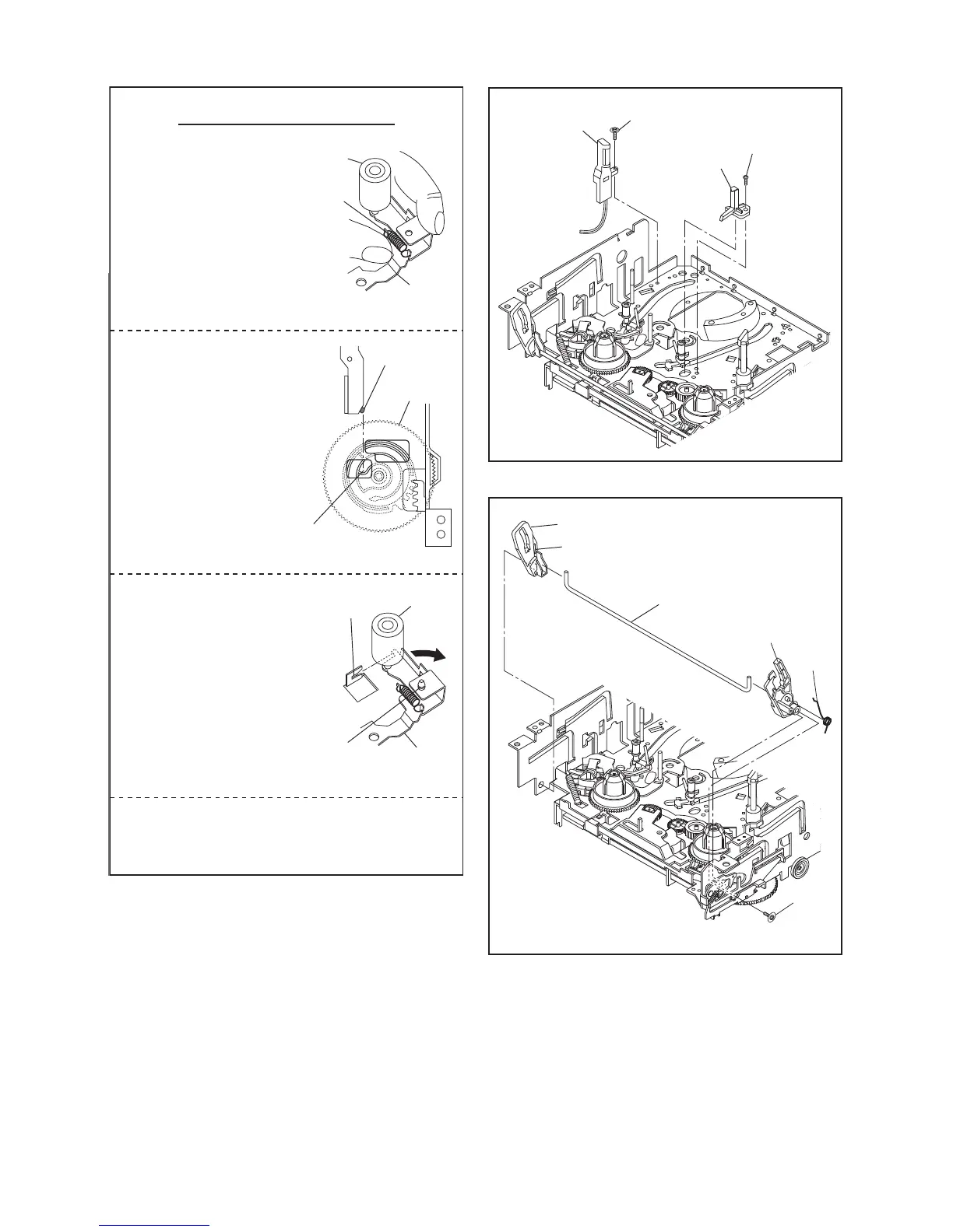
Fig. DM8H-1
Pin of [12]
Pin of [10]
Groove of [27]
View for A
When reassembling [10] and
[12], confirm that pin of [10]
and pin of [12] are in the
groove of [27] as shown.
[27]
Removal of [11]
1) Remove screw (S-4A).
2) Unhook spring (P-2).
3) Release (L-4) while
holding [12] with a
finger.
4) Loosen a finger
holding [12] and
remove [11].
A
(S-4A)
Installation of [13] and [12]
Pin of [12]
Groove of [27]
Hook spring (P-3) up to [12]
and [13], then install them to
the specified position so that
[12] will be floated slightly
while holding [12] and [13].
(Refer to Fig. A.)
Fig. A
[13]
[12]
(P-3)
Fig. B (Top view)
Install pin of [12] in groove of [27].
(Refer to Fig. B.)
[27]
Press both [12] and [13] till the
groove of chassis pin appears,
and adjust [13] to the notch of
chassis. Then turn [13] a little
in the direction of the arrow
while pressing [12].
(Refer to Fig. C.)
Fig. C
Groove of
pin of chassis
Notch of
chassis
turn
[13]
[12]
Install [11] and [10] while holding [12].
(Refer to Fig. DM8H-1.)
Fig. DM8H-2
[14]
[15]
(S-6)
(S-5)
Fig. DM9H
[17]
[16]
(L-5)
[18]
(P-4)
(S-7)
Fig. DM10H
 Loading...