4
© 2011 - 2015 TOSHIBA TEC CORPORATION All rights reserved e-STUDIO5540C/6540C/6550C/5560C/6560C/6570C
DISASSEMBLY and REPLACEMENT
4 - 135
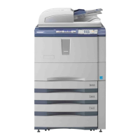
4.6.51 Temperature/humidity sensor (S12)
4.6.52 Toner motor interlock switch (SW3)
Notes:
When the toner motor interlock switch (SW3) is replaced or removed, be sure to perform the
operation check with the output check (test mode 03). If the installation is insufficient, this switch
is not performing properly. In this case, you may touch the rotating portions such as the gear in
the toner motor during the drive and could be injured as a result.
(1) Take off the laser unit cooling duct.
P. 4-38"4.4.2 Laser optical unit cooling
fan (front) (F22)"
(2) Remove 1 screw and then take off the
temperature/humidity sensor.
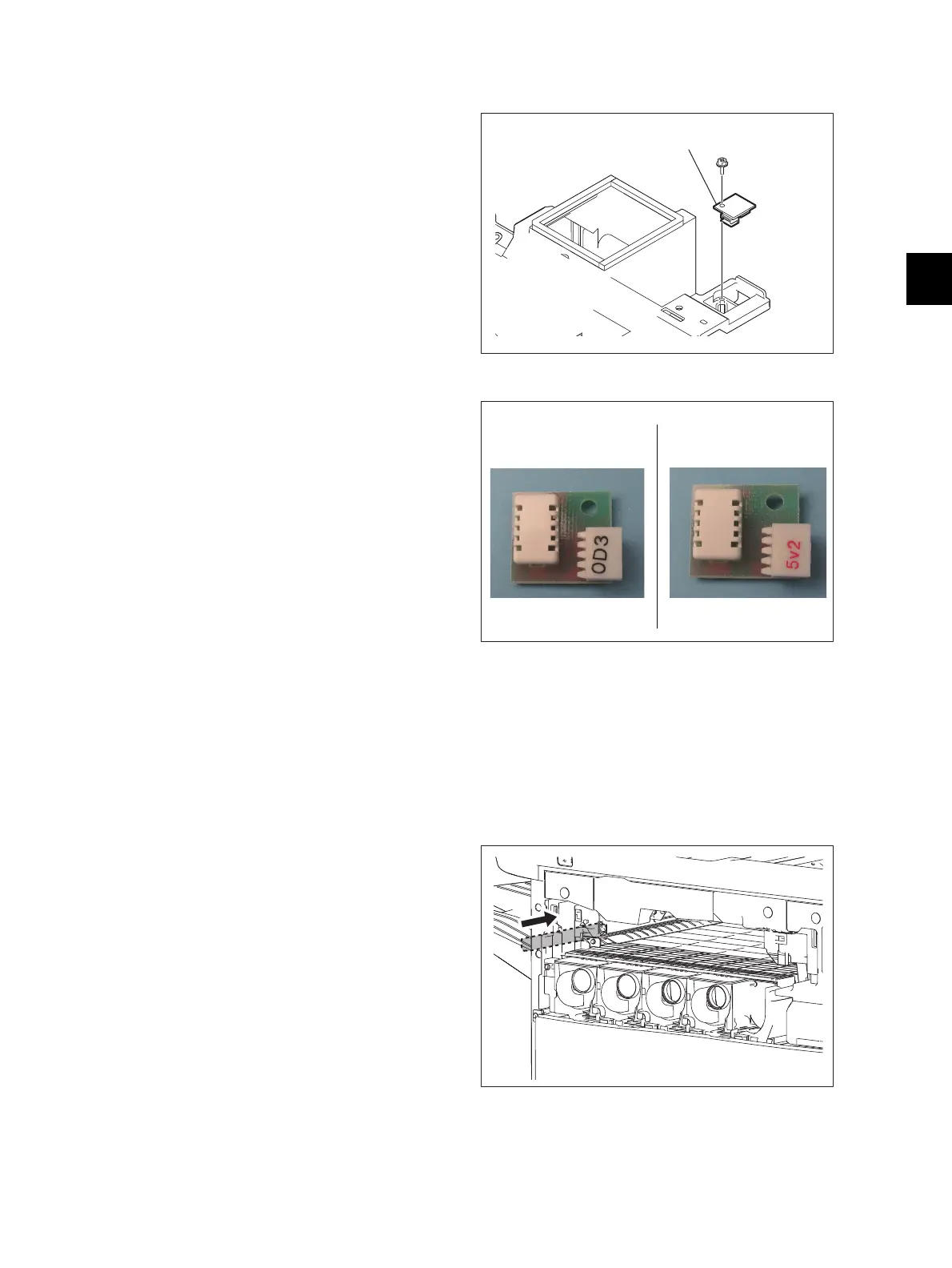
Notes:
Be sure to attach the temperature/humidity
sensor to the MFPs correspondingly since it
differs between e-STUDIO5540C/6540C/
6550C and e-STUDIO5560C/6560C/6570C.
• e-STUDIO5540C/6540C/6550C:
The mark on the connector is black.
• e-STUDIO5560C/6560C/6570C:
The mark on the connector is red.
Fig. 4-394
Fig. 4-395
(1) Take off the left corner cover.
P. 4-8"4.1.21 Left corner cover"
(2) Take off the bridge unit.
P. 4-213"4.10.11 Bridge unit"
(3) Insert 2 rails all the way in.
Fig. 4-396
Temperature/humidity sensor
e-STUDIO5540C/6540C/6550C e-STUDIO5560C/6560C/6570C
 Loading...