Quick Reference Guide - Page 7
Refrigerant Piping
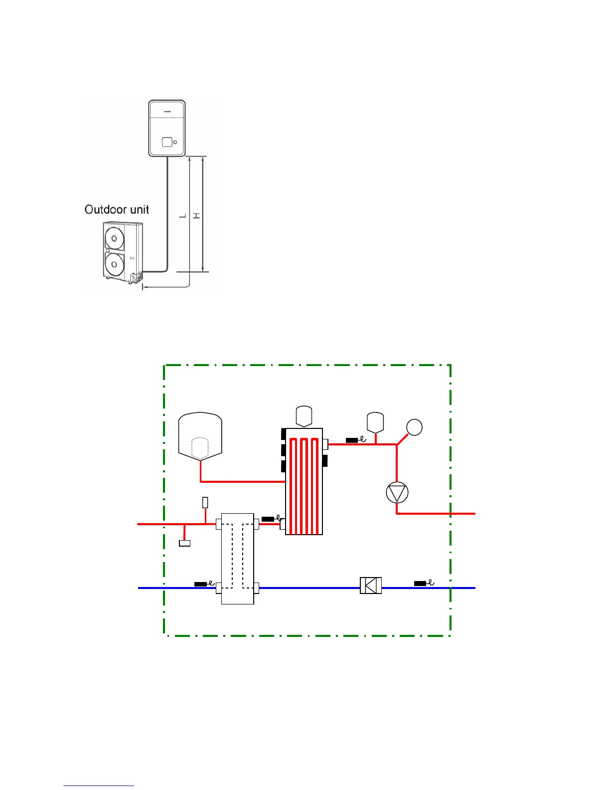
Refrigerant Pipe Lengths and Height
The length and height of the refrigeration pipe must be within the following values.
Minimum Pipe Length
HWS-802H-E : 5 m
HWS-1102H-E : 3 m
HWS-1402H-E : 3 m
Maximum Pipe Length and Height
H: Max. ±30 m (above or below)
L: Max. 30 m
Note
The maximum pipe length cannot be increased using additional
refrigerant.
Refrigeration and Water Cycle Diagrams
Hydro Unit
Pressure
relief
Air vent valve
Pressure
Gauge
valve
Expansion vessel
THO
Sensor
TWI
Sensor
TWO
Sensor
TC
Sensor
Thermal
Protector
Hi_P_Switch
Pump
Water Out
Refrigerant pipe
(1 1/4")
at gas side
Flow_Switch
Backup heater
Water Heat exchanger
Water IN
(1 1/4")
Refrigerant pipe
at liquid side
(Outer ø9.52)
P_Sensor
(Outer ø15.88)
 Loading...