EasyManua.ls Logo

Toshiba HWT-801HRW-E User Manual

Toshiba HWT-801HRW-E
300 pages
To Next Page IconTo Next Page
Page #1 background imageLoading...
Page #1 background image
1
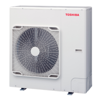
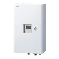
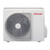
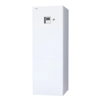
AIR TO WATER HEAT PUMP
Service Manual
FILE No. AE0-2203W
-All In One Type-
Model name:
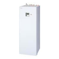
Hydro unit
HWT-602S21SM3W-E(TR)
HWT-602S21SM6W-E(TR)
HWT-602S21ST6W-E(TR)
HWT-602S21MM3W-E(TR)
HWT-602S21MM6W-E(TR)
HWT-602S21MT6W-E(TR)
HWT-1102S21SM3W-E(TR)
HWT-1102S21SM6W-E(TR)
HWT-1102S21ST6W-E(TR)
HWT-1102S21ST9W-E(TR)
HWT-1102S21MM3W-E(TR)
HWT-1102S21MM6W-E(TR)
HWT-1102S21MT6W-E(TR)
HWT-1102S21MT9W-E(TR)
HWT-1402S21SM3W-E(TR)
HWT-1402S21SM6W-E(TR)
HWT-1402S21ST6W-E(TR)
HWT-1402S21ST9W-E(TR)
HWT-1402S21MM3W-E(TR)
HWT-1402S21MM6W-E(TR)
HWT-1402S21MT6W-E(TR)
HWT-1402S21MT9W-E(TR)
Outdoor unit
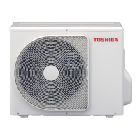
HWT-401HW-E(TR)
HWT-601HW-E(TR)
HWT-801HW-E(TR)
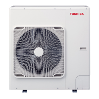
HWT-1101HW-E(TR)
HWT-1401HW-E(TR)
HWT-801HRW-E
HWT-1101HRW-E
HWT-1401HRW-E
HWT-801H8W-E
HWT-1101H8W-E
HWT-1401H8W-E
HWT-801H8RW-E
HWT-1101H8RW-E
HWT-1401H8RW-E

Table of Contents

Other manuals for Toshiba HWT-801HRW-E

Questions and Answers:

Toshiba HWT-801HRW-E Specifications

General IconGeneral
ModelHWT-801HRW-E
CategoryHeat Pump
TypeAir to Water
RefrigerantR410A
Heating Capacity8.0 kW
Power Supply230V, 50Hz, 1-Phase
Noise Level52 dB

Summary

1 Specifications

6 Refrigerant (R32)

Information and safety guidelines concerning R32 refrigerant.

6-1.Safety during installation / servicing

Crucial safety precautions for R32 handling during installation and servicing.

6-4.Recharging of refrigerant

Step-by-step instructions for recharging the refrigerant system.

6-6-7.Recovering refrigerant

Procedure for safely recovering refrigerant from the system.

6-7.Charging additional refrigerant

Guidelines and restrictions for adding refrigerant to the system.

6-8.General safety precautions for using R32 refrigerant

Critical safety guidelines for working with R32 refrigerant.

6-8-1.Recovery

Detailed procedures and safety measures for refrigerant recovery.

6-8-2.Decommissioning

Steps and safety precautions for decommissioning the unit.

8 Method of failure diagnosis

8-1.Matters to be confirmed first

Initial checks and confirmations before proceeding with failure diagnosis.

8-3.Outline of the determination diagram

Overview of the failure diagnosis decision tree.

8-3-2.How to determine from the check code on the remote controller

Method for identifying failures using remote controller check codes.

8-3-4.How to diagnose by check code

Detailed diagnostic actions based on specific check codes.

8-4.Diagnosis flow chart for each check code

Visual flowcharts for diagnosing specific failure codes.

8-4-1.Hydro unit failure detection

Diagnostic flowcharts for failures detected in the hydro unit.

8-4-2.Outdoor unit failure detection

Flow charts for diagnosing failures detected in the outdoor unit.

8-4-3.Temperature sensor, temperature-resistance characteristic table

Data table showing sensor resistance versus temperature characteristics.

8-6.Brief method for checking the key components

Simplified methods for checking critical system components.

9 Hydro unit and outdoor unit settings

10 Replacement of the service PC board

1. Hydro unit

Procedure for replacing the hydro unit's main PC board.

2. Outdoor unit

Procedure for replacing the outdoor unit's PC board.

11 How to exchange main parts

1. Hydro Unit

Procedures for replacing parts within the hydro unit.

13 Periodic inspection items

14 Part exploded view, part list

Related product manuals