26 I TOSHIBA26 I TOSHIBA
Optional inputs on the hydro unit
This unit has eight inputs. Two of the inputs can be selected
with the DN. The below table shows the input functions that
can be selected and the basic settings.
Potential-free contacts
Entry points (default setting)
I/P 1 Room thermostat input for heating
I/P 2 Room thermostat input for cooling
I/P 3 Domestic hot water tank thermostat input
I/P 4 Switching input for heating/cooling mode
I/P 5 Heating/cooling mode ON/OFF
I/P 6 Hot water mode ON/OFF
I/P 7 (DN: B6) 0: Emergency stop input
I/P 8 (DN: B6) 0: Not used
Selectable entry points (DN: B6)
DN:
B6
CN21 Point
0
8-10 Emergency stop input
9-10 Not used
1
8-10 TEMPO control input 1
9-10 Not used
2
8-10 TEMPO control input 2
9-10 Not used
3
8-10 Forcefully switch off emergency heating
9-10
Forcefully switch off hot water tank
heating
4
8-10 Smart Grid network input 1
9-10 Smart Grid network input 2
– 15 –
Hydro Unit
Installation Manual
Additional Hydro Unit outputs
This unit has four output ports. They are
selectable by DN. Table1 shows the selectable
output functions and default settings.
Volt free contact – specification show below:
AC230 V; 0.5 A (maximum)
DC24 V; 1 A (maximum)
Minimum current; 10 mA
▼ Table1
0: Alarm output
Open: No alarm
Close: Alarm
1: Compressor operation output
Open: Compressor is stopping
Close: Compressor is operating
2: Defrost operation output
Open: Unit is not defrost operating
Close: Unit is defrost operating
3: Boiler control output
Open: Normal operation
Close: Boiler operation output
4: During safety or protection control running
Open: Normal operation
Close: Release control running
5: During backup heater running
Open: Backup heater not running
Close: Backup heater running
6: During hot water cylinder heater running
Open: Hot water cylinder heater not running
Close: Hot water cylinder heater running
7: Heating operation output
Open: Not heating operation
Close: Heating operation
(Include HP, Heater and thermo off.)
8: Cooling operation output
Open: Not cooling operation
Close: Cooling operation
(Include HP and thermo off.)
9: Hot water operation output
Open: Not hot water operation
Close: Hot water operation
(Include HP, Heater and thermo off.)
Default setting
O/P 1 (DN: 6CA) Alarm output
O/P 2 (DN: 6CC) Defrost operation output
O/P 3 (DN: 6CD) Boiler control output
O/P 4 (DN: 6CB) Compressor operation output
Selectable output items (DN: 6CA~6CD)
0 Alarm output
1 Compressor operation output
2 Defrost operation output
3 Boiler control output
4 Safety or protection control running
5 During backup heater running
6 During hot water cylinder heater running
7 Heating operation output
8 Cooling operation output
9 Hot water operation output
common line
MCC-1755
O/P 4
common line
CN22
6
5
4
3
2
1
O/P 2
O/P 3
O/P 1
Hydro Unit sub PCB
Locally procured
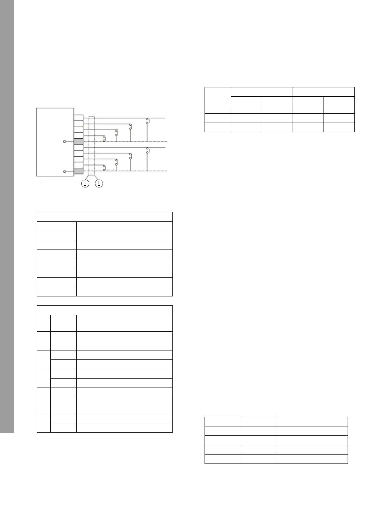
Optional inputs to Hydro Unit
This unit has eight input ports. 2 ports of them are
selectable by DN. Table2 shows the selectable
input functions and default settings.
Non-voltage contacts
▼ Table2
I/P1 & I/P2: Room thermostat input
• Setting: DN [6B3] = 1
• Non-voltage contacts
Thermostat operation
I/P3: Hot water tank thermostat input
• This function is used, when the customer use the
local hot water tank.
• Setting: DN [6B2] = 1
• Non-voltage contacts
Open: Reached setting temperature
Close: Not reached setting temperature
I/P4: Heating/cooling mode switching input
• Non-voltage contact
Open: Heating mode
Close: Cooling mode
I/P5: Heating/cooling operation ON/OFF input
• Non-voltage contact
Open: Operation OFF (Remote controller OFF)
Close: Operation ON (Remote controller ON)
I/P6: Hot water operation ON/OFF input
• Non-voltage contact
Open: Operation OFF (Remote controller OFF)
Close: Operation ON (Remote controller ON)
I/P7 & I/P8: Connection to a Smart Grid network (SG
Ready)
• Non-voltage contacts
• The operating mode is controlled through volt free
contacts incorporated into the energy meter.
• Setting: DN [B6] = 4
0: Open, 1: Close
Input items (Default setting)
I/P 1 Room thermostat input for heating
I/P 2 Room thermostat input for cooling
I/P 3 Hot water tank thermostat input
I/P 4 Heating/cooling mode switching input
I/P 5 Heating/cooling operation ON/OFF
I/P 6 Hot water operation ON/OFF
I/P 7 (DN: B6) 0: Emergency shutdown input
I/P 8 (DN: B6) 0: None
Selectable input items (DN: B6)
DN:
B6
CN21 Item
0
8-10 Emergency Shutdown input
9-10 None
1
8-10 TEMPO control input 1
9-10 None
2
8-10 TEMPO control input 2
9-10 None
3
8-10 Forcibly turn off the backup heater
9-10
Forcibly turn off the hot water tank
heater
4
8-10 Smart Grid network input 1
9-10 Smart Grid network input 2
MCC-1755
I/P 4
common
line
CN21
1
2
3
4
5
6
7
8
9
10
common
line
I/P 3
I/P 2
I/P 1
I/P 8
I/P 7
I/P 6
I/P 5
Locally procured
CN21
Heating Cooling
Reach Not reach Reach Not reach
1-5 (I/P1) open close - -
2-5 (I/P2) - - close open
I/P7 I/P8 Operation Mode
0 0 Restricted Operation
1 0 System OFF
0 1 Normal Operation
1 1 System Forced ON
29-EN 30-EN
+00_2F30151001_01EN.book 15 ペ?ジ 2021?2?3? ??? ??2?9?
I/P1 & I/P2 room thermostat input
• Setting: DN [6B3] = 1
• Potential-free contacts
Thermostat operation
CN21
Heating Cooling
Reach
Do not
reach
Reach
Do not
reach
1-5 (I/P1) Open Close - -
2-5 (I/P2) - - Close Open
I/P3: Hot water tank thermostat input
• This function is used when the customer uses the
local hot water tank.
• Setting: DN [6B2] = 1
• Potential-free contacts
Open: Set temperature reached
Close: Set temperature not reached
I/P4: Switching input for heating/cooling mode
• Potential-free contact
Open: Heating mode
Close: Cooling mode
I/P5: Heating/cooling mode ON/OFF input
• Potential-free contact
Open: Operation OFF (remote control OFF)
Close: Operation ON (remote control ON)
I/P5: Hot water mode ON/OFF input
• Potential-free contact
Open: Operation OFF (remote control OFF)
Close: Operation ON (remote control ON)
I/P7 I/P8: Connection to a Smart Grid network (SG
Ready)
• Potential-free contact
• The operating mode is controlled by voltage-free
contacts that are integrated in the energy meter.
• Setting: DN [B6] = 4
0: Open, 1: Close
I/P7 I/P8 Operating mode
0 0 Limited operation
1 0 System OFF
0 1 Standard operation
1 1 Forced system ON
OPTIONAL INPUTS ON THE HYDRO UNIT
 Loading...