EasyManua.ls Logo

Toshiba HWS-803H-E User Manual

Toshiba HWS-803H-E
212 pages
To Next Page IconTo Next Page
Page #1 background imageLoading...
Page #1 background image
Model name:
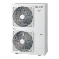
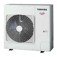
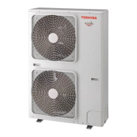
Outdoor Unit
HWS-803H-E(TR)
HWS-1103H-E(TR)
HWS-1403H-E(TR)
HWS-1103H8-E
HWS-1103H8R-E
HWS-1403H8-E
HWS-1403H8R-E
HWS-1603H8-E
HWS-1603H8R-E
AIR TO WATER HEAT PUMP
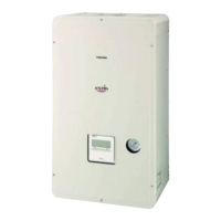
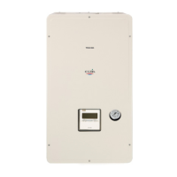
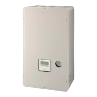
Hydro Unit
HWS-803XWHM3-E(TR)
HWS-803XWHT6-E(TR)
HWS-803XWHD6-E
HWS-803XWHT9-E
HWS-1403XWHM3-E(TR)
HWS-1403XWHT6-E(TR)
HWS-1403XWHD6-E
HWS-1403XWHT9-E(TR)
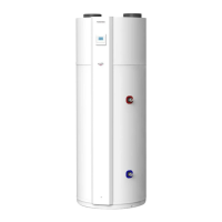
Hot Water Cylinder
HWS-1501CSHM3-E(-UK)
HWS-2101CSHM3-E(-UK)
HWS-3001CSHM3-E(-UK)
SERVICE MANUAL
A10-006

Table of Contents

Other manuals for Toshiba HWS-803H-E

Questions and Answers:

Toshiba HWS-803H-E Specifications

General IconGeneral
ModelHWS-803H-E
Heating Capacity8.0 kW
EER3.2
RefrigerantR410A
TypeHeat Pump
Power Supply230V / 1Ph / 50Hz

Summary

Safety Precautions

Understanding Indications and Symbols

Explanation of danger, warning, caution indications and their associated symbols.

High Voltage and Electrical Hazards

Critical warnings about high voltage, capacitor discharge, and proper grounding.

General Safety Guidelines

Precautions regarding part usage, children's safety, insulation, fire hazards, and water leaks.

Operational Safety and Checks

Safety measures for insulation testing, ventilation, electrical shock prevention, and post-repair checks.

Handling Precautions

Cautions for wearing gloves, cooling checks, and tightening procedures.

New Refrigerant R410A Safety

R410A Installation and Service Safety

Safety guidelines for installing and servicing units using R410A refrigerant.

Refrigerant Piping Installation

Procedures and safety notes for installing refrigerant pipes, including steel and copper types.

Piping Material Processing

Detailed steps for cutting, flaring, and preparing piping materials for R410A systems.

Flare Connection Procedures

Guidelines and precautions for correctly connecting flared pipe joints.

Necessary Tools for R410A

List of specialized and general tools required for R410A system servicing.

Refrigerant Recharging Procedure

Step-by-step guide for safely recharging the system with refrigerant.

Pipe Brazing Materials and Methods

Information on brazing metals, flux, and the brazing process to prevent oxidation.

Product Specifications

Unit Specifications Overview

Technical details including heating/cooling capacity, power, and dimensions for various models.

Hydro Unit Dimensions and Weight

Detailed dimensions, net weight, and color specifications for the Hydro Unit.

Outdoor Unit Dimensions and Components

Drawings and dimensions for the Hydro unit, showing connection points and overall size.

Outdoor Unit Dimensions and Components

Drawings and dimensions for the Outdoor unit, detailing various connection outlets and mounting holes.

Hot Water Cylinder Dimensions

Exploded views and overall dimensions for different Hot Water Cylinder models.

Wiring Diagrams

Hydro Unit Wiring Diagram

Detailed wiring diagram for the Hydro Unit, showing component connections and terminal blocks.

Outdoor Unit Single Phase Wiring

Wiring diagram for single-phase Outdoor Units, illustrating control board connections.

Outdoor Unit Three Phase Wiring

Wiring diagram for three-phase Outdoor Units, detailing PC board connections and components.

Hot Water Cylinder Unit Wiring

Wiring diagram for the Hot Water Cylinder Unit, showing sensor and heater connections.

Key Electric Component Ratings

Hydro Unit Component Ratings

Electrical ratings and specifications for key components of the Hydro Unit.

Outdoor Unit Component Ratings

Electrical ratings for compressors, fan motors, and coils in the Outdoor Unit (HWS-803H-E).

Outdoor Unit Component Ratings

Electrical ratings for key components in Outdoor Units (HWS-1103H-E, 1403H-E).

Outdoor Unit Component Ratings

Electrical ratings for components in Outdoor Units (HWS-1103H8(R)-E, etc.).

Hot Water Cylinder Component Ratings

Electrical ratings for the Hot Water Cylinder heater and sensors.

Water Heat Exchange Control Board Layout

Diagram showing the layout and connectors of the Water Heat Exchange Control Board.

Outdoor Control Board (Single Phase) Layout

Diagram identifying components and connectors on the single-phase Outdoor Control Board.

Outdoor Control Board (Single Phase) Layout

Detailed view of the single-phase Outdoor Control Board with component identification.

Outdoor Unit Control Board (3 Phase) Layout

Layout of the 3-phase Outdoor Unit Control Board (Compressor IPDU).

Outdoor Unit Control Board (3 Phase) Layout

Layout of the Fan Motor IPDU board for 3-phase Outdoor Units.

Outdoor Unit Control Board (3 Phase) Layout

Layout of the Interface (CDB) board for 3-phase Outdoor Units.

Outdoor Unit Control Board (3 Phase) Layout

Layout of the Noise Filter board for 3-phase Outdoor Units.

System Diagrams

Water System Diagram

Schematic illustrating the water circuit, including components like pumps, valves, and heaters.

Water Circuit Installation Examples

Diagrams showing various installation configurations for the water circuit.

Refrigeration Cycle Diagram

Schematic showing the refrigeration cycle for different unit models.

Refrigeration Cycle Diagram

Refrigeration cycle diagrams for various models, illustrating refrigerant flow.

Operational Description

Basic Operation Overview

Description of basic operations like hot water supply, heating, and cooling.

Operation Modes and Control Methods

Explanation of various operation modes and their control logic.

Hot Water Supply Operation Details

Specific conditions and procedures for hot water supply operation.

Heating Operation Details

Specific conditions and procedures for heating operation, including temperature settings.

Cooling Operation Details

Specific conditions and procedures for cooling operation.

Simultaneous and Priority Operations

Managing simultaneous hot water, heating, and cooling operations with priority settings.

Boiler Control Functions

How the boiler integrates with heat pump operations and its control settings.

Hot Water Boost Operation

Procedure for quickly heating water using the heat pump and cylinder heater.

Anti-Bacteria Operation

Procedure for regularly raising hot water temperature to prevent bacterial growth.

Night Setback and Frost Protection

Settings for reducing energy use at night and preventing frost damage.

Auto Operation and Low-Noise Mode

Automatic temperature adjustments and settings for reducing operating noise at night.

Hydro Unit Control Functions

Detailed control logic for the Hydro Unit, including capacity and heater management.

Heater Control Logic

How backup and booster heaters are controlled based on temperature and operation status.

Circulation Pump and Mixing Valve Control

Control methods for circulation pumps and the mixing valve for temperature regulation.

Room Temperature Control Methods

Strategies for controlling room temperature using remote controls and thermostats.

Thermostat Control Logic

Detailed logic for heating and cooling thermostat operations.

Force Stop and Restart Control

Methods for externally controlling unit stop and restart operations.

Heat Pump Operation Limit Control

Limiting heat pump operation based on external signals for peak power management.

Output Signal Controls

Description of output signal controls for error detection and boiler status.

Hydro Unit Q-H Characteristics

Performance curves (flow rate vs. pump head) for the Hydro Unit.

Automatic Restart and Freeze Prevention

Unit behavior after power outages and controls to prevent pipe freezing.

High Return Water Protection

Protection mechanism against high return water temperatures from external boilers.

Outdoor Unit Control Functions

Control logic for Outdoor Unit components like PMV and discharge temperature.

Current Release and Fan Control

Control based on current limits, fan speed regulation, and defrosting procedures.

Defrosting Control Logic

Mechanism for defrosting the outdoor heat exchanger using a 4-way valve.

Winding Heating and Protection Controls

Controls for compressor winding heating, short circuit, and over current protection.

Pressure and Thermostat Controls

High pressure release, switch functions, and compressor case thermostat operations.

Bottom Plate Heater Control

Control logic for the bottom plate heater based on outdoor temperature.

Defect Diagnosis Procedures

General Defect Diagnosis Overview

Outline of the defect diagnosis process, including initial checks and symptom understanding.

Initial Confirmation Steps

Essential first checks: power supply, wiring, and sensor installation.

Non-Defective Operations Identification

Identifying normal operations that may appear as defects.

Defect Determination Using Check Codes

Flowchart for diagnosing defects based on remote controller check codes.

Interpreting Remote Controller Check Codes

Guidance on how to determine defects from remote controller error codes.

Canceling Check Codes

Procedure for clearing check codes from the remote controller.

Diagnosing Errors by Code

Detailed troubleshooting steps for specific error codes (A01-A05).

Diagnosing Errors by Code

Troubleshooting steps for error codes E03, E04, F03, F10, F11, F14.

Diagnosing Errors by Code

Troubleshooting steps for error codes F17, F18, F19, F20, F23, F29, F30, L07.

Diagnosing Errors by Code

Troubleshooting steps for error codes L09, L16, P03, P04.

Diagnosing Errors by Code

Troubleshooting steps for error codes P05, P07, P15, P19.

Diagnosing Errors by Code

Troubleshooting steps for error codes P20, P22, P26, P29.

Diagnosing Errors by Code

Troubleshooting steps for outdoor unit errors (no specific code).

Hydro Unit Failure Diagnosis Flowcharts

Flowcharts for diagnosing Hydro Unit failures, starting with pump flow determination.

Hydro Unit Failure Diagnosis Flowcharts

Flowcharts for diagnosing A02, A03, A04, A05 errors in the Hydro Unit.

Hydro Unit Failure Diagnosis Flowcharts

Flowcharts for diagnosing A07, A08, A09 errors in the Hydro Unit.

Hydro Unit Failure Diagnosis Flowcharts

Flowcharts for diagnosing A11, A12 errors in the Hydro Unit.

Hydro Unit Failure Diagnosis Flowcharts

Flowcharts for diagnosing E04, F03 errors in the Hydro Unit.

Hydro Unit Failure Diagnosis Flowcharts

Flowcharts for diagnosing F04, F06, F07 errors in the Hydro Unit.

Hydro Unit Failure Diagnosis Flowcharts

Flowcharts for diagnosing F08, F10, F11 errors in the Hydro Unit.

Hydro Unit Failure Diagnosis Flowcharts

Flowcharts for diagnosing F14, F17, F18 errors in the Hydro Unit.

Hydro Unit Failure Diagnosis Flowcharts

Flowcharts for diagnosing F19, F20, F23 errors in the Hydro Unit.

Hydro Unit Failure Diagnosis Flowcharts

Flowcharts for diagnosing F29, F30, L07 errors in the Hydro Unit.

Hydro Unit Failure Diagnosis Flowcharts

Flowcharts for diagnosing L09, L16 errors in the Hydro Unit.

Outdoor Unit Failure Diagnosis

Procedure for diagnosing outdoor unit failures based on check codes and LED indications.

Outdoor Unit LED Indication Method

Guide to interpreting LED indicators on the outdoor control board for failure detection.

Outdoor Unit Failure Diagnosis Procedures

Step-by-step diagnosis procedure for the H01 check code (Compressor fails).

Outdoor Unit Failure Diagnosis Procedures

Diagnosis procedures for H02 (Compressor lock) and H04 (Case thermostat operation) errors.

Outdoor Unit Failure Diagnosis Procedures

Diagnosis procedures for L10, L29, P03 errors related to communication and temperature sensors.

Outdoor Unit Failure Diagnosis Procedures

Diagnosis procedure for P04 (High pressure error) and related LED indications.

Outdoor Unit Failure Diagnosis Procedures

Diagnosis procedures for P05 (Power source failure) and P07 (Heat sink overheat).

Outdoor Unit Failure Diagnosis Procedures

Diagnosis procedure for P15 (Gas leakage detection).

Outdoor Unit Failure Diagnosis Procedures

Diagnosis procedure for P19 (4-way valve invert failure).

Outdoor Unit Failure Diagnosis Procedures

Diagnosis procedure for P20 (High pressure protection operation).

Outdoor Unit Failure Diagnosis Procedures

Diagnosis procedures for P22 (Blower system failure), P26 (Compressor drive element short), and P29 (Position detection).

Outdoor Unit Failure Diagnosis Procedures

Diagnosis for errors related to discharge temperature, heat exchanger, and sensors.

Outdoor Unit Failure Diagnosis Procedures

Diagnosis for errors related to outside air temperature, suction, and heat sink sensors.

Outdoor Unit Failure Diagnosis Procedures

Diagnosis for EEPROM failure and related LED indications.

Temperature Sensor Characteristics

Resistance values and graphs for temperature sensors at various temperatures.

PC Board Switch Operation Checks

Procedures for checking component operations using PC board switches.

Key Component Checking Methods

Brief methods for checking key components of the Hydro Unit.

Hydro Unit Component Resistance Checks

Procedures for measuring resistance of sensors and the circulating pump in the Hydro Unit.

Outdoor Unit Component Resistance Checks

Procedures for measuring resistance of compressor, fan motor, valves, and sensors in the Outdoor Unit.

Unit Settings and Configuration

Hydro Unit Switch Settings

Overview of DIP switch settings for system configuration on the Hydro Unit.

Function Code Settings for Hydro Unit

Instructions on how to set function codes (FC) for Hydro Unit parameters.

Remote Controller Function Code Settings

Instructions on setting function codes via the remote controller.

Function Code Reference Table

A comprehensive table listing function codes, items, details, and first shipment values.

Resetting Hydro Unit Function Codes

Procedure for resetting Hydro Unit function codes after PCB replacement.

Resetting Remote Controller Function Codes

Information on the inability to reset remote controller function codes to default values.

Performing Trial Operations

Steps to perform trial operations for hot water supply, heating, and cooling modes.

Auto Curve Setting Configuration

How to configure flexible Auto-Curve settings for temperature control.

Time Setting Procedure

Instructions for setting the current time and day on the remote controller.

Scheduled Operation Setup

Guide to setting up scheduled operations for various modes and temperatures.

Frost Protection Setting

How to enable frost protection mode for maintaining room temperature.

Night Operation Settings

How to adjust heating or cooling temperatures for energy saving during night hours.

Anti-Bacteria Setting Procedure

Steps to raise hot water temperature to prevent bacteria growth.

Hot Water Boost Setting

How to set and activate the hot water boost function for rapid heating.

Night Time Low-Noise Setting

How to enable low-noise operation during nighttime hours.

Forced Defrosting Setting

Procedure to activate the forced defrosting mode for the outdoor unit.

Displaying Sensor and Setting Data

How to access the service monitor mode to view sensor data and settings.

Failure History Calling Function

Procedure to recall and view previous failure details.

Outdoor Unit Settings and Operations

Refrigerant Recovery Operation

Procedure for performing environmentally friendly refrigerant recovery.

Outdoor Unit DIP Switch and Jumper Settings

Settings for existing piping, power save, snow prevention, and defrosting time.

Service Support Functions Overview

Overview of service support functions using DIP switches and push-button switches.

LED Indication Switching

How to switch and interpret LED indications on the outdoor control board.

Abnormality Indication via LEDs

Understanding current and latest abnormalities indicated by LEDs D800-D804.

Sensor, Current, and Compressor Data Display

How to check sensor values, current, compressor frequency, and PMV position.

Special Operations for Maintenance

Using SW801 and SW804 for special operations like refrigerant recovery and fan control.

Special Operation Details

Specific procedures for special operations like PMV control and 4-way valve relay.

Service P.C. Board Replacement

Jumper Wire and DIP Switch Settings

Setting jumper wires and DIP switches for different models and service functions.

Model Switching with Jumpers

Using jumpers J800-J803 to select the correct model for the P.C. board.

Main Parts Exchange Procedures

Hydro Unit Parts Replacement

General procedures for replacing parts in the Hydro Unit, including safety warnings.

Replacing Hydro Unit Components

Step-by-step instructions for replacing the front panel, electric parts covers, and remote controller.

Replacing Hydro Unit Control Boards

Procedures for replacing the Water Heat Exchanger board and Relay board.

Replacing Hydro Unit Electronic Assemblies

Procedures for replacing the electric parts assembly, side board, upper board, and bottom board.

Replacing Hydro Unit Water Circuit Parts

Procedures for replacing the expansion vessel, relief valve, air vent valve, pump, and flow switch.

Replacing Hydro Unit Heater and Sensors

Procedures for replacing the heater assembly and various temperature sensors.

Replacing Hydro Unit Water Heat Exchanger Assembly

Procedure for removing and attaching the water heat exchanger assembly.

Outdoor Unit Common Procedure

General steps for disassembling and assembling the Outdoor Unit (HWS-803H-E).

Replacing Outdoor Unit Cabinets

Procedures for removing and attaching the outlet cabinet and side cabinet.

Replacing Outdoor Unit Electric Parts

Procedures for replacing the control board and reactor.

Replacing Outdoor Unit Fan Motor

Step-by-step instructions for removing and installing the fan motor.

Replacing Compressor and Related Parts

Procedure for removing and attaching the compressor and its lead.

Replacing PMV Coil and Fan Guard

Procedures for replacing the PMV coil and the fan guard.

Outdoor Unit Parts Replacement (HWS-1103H8(R)-E, etc.)

Common procedures for replacing parts on specific Outdoor Unit models.

Replacing Outdoor Unit Cabinets (HWS-1103H8(R)-E, etc.)

Procedures for removing and attaching the discharge port cabinet and side cabinet.

Replacing Outdoor Unit Inverter Assembly

Procedure for removing and attaching the inverter assembly.

Replacing Outdoor Unit Interface Board

Procedure for removing and attaching the interface board (control board).

Replacing Outdoor Unit Fan-IPDU Board

Procedure for removing and attaching the Fan-IPDU board.

Replacing Outdoor Unit Noise Filter Board

Procedure for removing and attaching the noise filter board.

Replacing Outdoor Unit Compressor IPDU Board

Procedure for removing and attaching the compressor IPDU board.

Replacing Outdoor Unit Fan Motor

Procedure for removing and attaching the fan motor.

Replacing Compressor Lead

Procedure for removing and attaching the compressor lead.

Replacing PMV Coil and Fan Guard

Procedures for replacing the PMV coil and fan guard.

Periodic Inspection Schedule

Hydro Unit Periodic Inspection

Inspection items and frequency for the Hydro Unit components.

Outdoor Unit Periodic Inspection

Inspection items and frequency for the Outdoor Unit components.

Hot Water Cylinder Periodic Inspection

Inspection items and frequency for the Hot Water Cylinder components.

Part Exploded Views and Lists

Hydro Unit Exploded View and Part List

Visual breakdown and part list for the Hydro Unit.

Hydro Unit Component Part Numbers

Detailed part numbers and quantities for Hydro Unit components.

Outdoor Unit (HWS-803H-E) Exploded View

Exploded view of the Outdoor Unit (HWS-803H-E) showing component locations.

Outdoor Unit (HWS-803H-E) Part List

Part list and quantities for the HWS-803H-E Outdoor Unit.

Outdoor Unit (HWS-1103H-E, 1403H-E) Exploded View

Exploded view of the Outdoor Unit (HWS-1103H-E, 1403H-E) with numbered parts.

Outdoor Unit (HWS-1103H-E, 1403H-E) Part List

Part list and quantities for the HWS-1103H-E and HWS-1403H-E Outdoor Units.

Outdoor Unit (HWS-1103H8(R)-E, etc.) Exploded View

Exploded view of the Outdoor Unit (HWS-1103H8(R)-E, 1403H8(R)-E, 1603H8(R)-E).

Outdoor Unit (HWS-1103H8(R)-E, etc.) Part List

Part list and quantities for HWS-1103H8(R)-E, 1403H8(R)-E, 1603H8(R)-E Outdoor Units.

Inverter Assembly (HWS-803H-E) Exploded View

Exploded view of the Inverter Assembly for HWS-803H-E, showing component layout.

Inverter Assembly (HWS-803H-E) Part List

Part list for the Inverter Assembly of HWS-803H-E.

Inverter Assembly (HWS-1103H-E, 1403H-E) Exploded View

Exploded view of the Inverter Assembly for HWS-1103H-E, 1403H-E.

Inverter Assembly (HWS-1103H-E, 1403H-E) Part List

Part list for the Inverter Assembly of HWS-1103H-E, 1403H-E.

Related product manuals