Home
Toshiba
Heat Pump
HWS-P804XWHM3-E1(TR)
Toshiba HWS-P804XWHM3-E1(TR) - User Manual
172 pages
Manual
Specs
Ask a question
Save Page as PDF
To Next Page
To Next Page
Loading...
Model name:
Outdoor unit
HWS-P804HR-E1(TR)
HWS-P1104HR-E1(TR)
AIR TO WATER HEAT PUMP
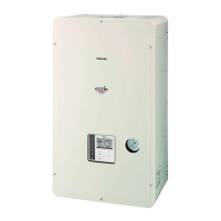
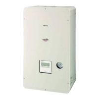
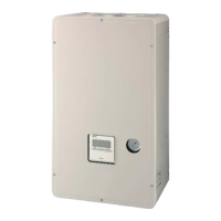
Hydro unit
HWS-P804XWHM3-E1(TR)
HWS-P804XWHT6-E1(TR)
HWS-P804XWHT9-E1
HWS-P1104XWHM3-E1(TR)
HWS-P1104XWHT6-E1(TR)
HWS-P1104XWHT9-E1(TR)
Service Manual
FILE No. A10-1503
AMP Air Conditioning
www.ampair.co.uk | sales@ampair.co.uk
2
Table of Contents
Main Page
Default Chapter
1
Service Manual
1
Table of Contents
2
1 Safety Precautions
4
2 Refrigerant (R410A)
7
2-1.Safety During Installation and Service
7
2-2.Installing Refrigerant Pipe
8
2-2-1.Steel Pipe and Joint
8
2-2-2.Processing of Piping Materials
9
2-3.Tools
11
2-3-1.Necessary Tools
11
2-4.Recharging of Refrigerant
12
2-5.Brazing of Pipes
14
2-5-1.Materials of Brazing
14
2-5-2.Flux
14
2-5-3.Brazing
14
3 Specifications
16
4 Outside Drawing
18
4-1.Hydro Unit
18
4-2.Outdoor Unit
19
4-3.Hot Water Cylinder
20
5 Wiring Diagram
21
5-1.Hydro Unit
21
5-2.Outdoor Unit
22
5-3.Hot Water Cylinder Unit
23
6 Key Electric Component Rating
24
6-1.Hydro Unit
24
6-2.Outdoor Unit
26
6-3.Hot Water Cylinder Unit
27
6-4.Water Heat Exchange Control Board
28
6-5.Outdoor Control Board
29
7 Refrigeration Cycle / Water System Diagram
30
7-1.Water System Diagram
30
7-2.Refrigeration Cycle System Diagram
32
8 Operational Description
33
9 Method of Defect Diagnosis
75
9-1.Matters to be Confirmed First
75
9-1-1.Check the Power Supply Voltage
76
9-1-2.Check for any Miswiring of the Connection Cables between the Hydro Unit and the Outdoor Unit
76
9-1-3.About the Installation of the Temperature Sensor
76
9-2.Non-Defective Operation (Program Operation)
76
9-3.Outline of the Determination Diagram
77
9-3-1.Procedure of Defect Diagnosis
77
9-3-2.How to Determine from the Check Code on the Remote Controller
77
9-3-3.How to Cancel a Check Code on the Remote Controller
77
9-3-4.How to Diagnose by Error Code
78
9-4.Diagnosis Flow Chart for each Error Code
85
9-4-1.Hydro Unit Failure Detection
85
9-4-2.Outdoor Unit Failure Detection
103
9-4-3.Temperature Sensor, Temperature-Resistance Characteristic Table
114
9-5.Operation Check by PC Board Switch
115
9-5-1.Operation Check Mode
115
9-6.Brief Method for Checking the Key Components
116
9-6-1.Hydro Unit
116
9-6-2.Outdoor Unit
117
10 Hydro Unit and Outdoor Unit Settings
119
11 Replacement of the Service PC Board
144
12 How to Exchange Main Parts
145
13 For Cooling Installation
163
14 Periodic Inspection Items
164
15 Part Exploded View, Part List
165
Need help?
Do you have a question about the Toshiba HWS-P804XWHM3-E1(TR) and is the answer not in the manual?
Ask a question
Toshiba HWS-P804XWHM3-E1(TR) Specifications
Print Specification
General
Model
HWS-P804XWHM3-E1(TR)
Category
Heat Pump
Cooling Capacity (kW)
8.0
Heating Capacity (kW)
9.0
Power Supply
220-240V, 50Hz
Noise Level
52 dB
Related product manuals
Toshiba HWS-P805HR-E
184 pages
Toshiba HWS-P805XWHM3-E
184 pages
Toshiba HWS-P1105HR-E
184 pages
Toshiba HWS-P1105XWHT6-E
184 pages
Toshiba HWS-805H-E
29 pages
Toshiba HWS-803H-E
212 pages
Toshiba HWS-1603H8-E
212 pages
Toshiba HWS-1103H8-E
212 pages
Toshiba HWS-803XWHM3-E
58 pages
Toshiba HWS-802XWHM3-E
168 pages
Toshiba HWS-1403XWHM3-E
58 pages
Toshiba HWS-1402XWHT9-E
58 pages