EasyManua.ls Logo

Toshiba HWS-1603H8-E User Manual

Toshiba HWS-1603H8-E
212 pages
To Next Page IconTo Next Page
Page #1 background imageLoading...
Page #1 background image
Model name:
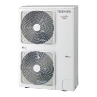
Outdoor Unit
HWS-803H-E(TR)
HWS-1103H-E(TR)
HWS-1403H-E(TR)
HWS-1103H8-E
HWS-1103H8R-E
HWS-1403H8-E
HWS-1403H8R-E
HWS-1603H8-E
HWS-1603H8R-E
AIR TO WATER HEAT PUMP
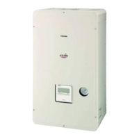
Hydro Unit
HWS-803XWHM3-E(TR)
HWS-803XWHT6-E(TR)
HWS-803XWHD6-E
HWS-803XWHT9-E
HWS-1403XWHM3-E(TR)
HWS-1403XWHT6-E(TR)
HWS-1403XWHD6-E
HWS-1403XWHT9-E(TR)
Hot Water Cylinder
HWS-1501CSHM3-E(-UK)
HWS-2101CSHM3-E(-UK)
HWS-3001CSHM3-E(-UK)
SERVICE MANUAL
A10-006

Table of Contents

Other manuals for Toshiba HWS-1603H8-E

Questions and Answers:

Toshiba HWS-1603H8-E Specifications

General IconGeneral
BrandToshiba
ModelHWS-1603H8-E
CategoryHeat Pump
LanguageEnglish

Summary

1 SAFETY PRECAUTIONS

Indications and Symbols

Explains safety indications (Danger, Warning, Caution) and symbols used in the manual.

2 New Refrigerant (R410A)

2-1. Safety During Installation and Service

Outlines critical safety measures for handling R410A refrigerant during installation and service.

2-2. Installing Refrigerant Pipe

Details procedures and specifications for installing refrigerant piping, including pipe types and joints.

2-3. Necessary Tools

Lists essential tools required for R410A installation and their interchangeability with conventional tools.

2-4. Recharging of Refrigerant

Provides a step-by-step procedure for recharging refrigerant in the system, including necessary configurations.

2-5. Brazing of Pipes

Covers materials, flux, and procedures for brazing pipes, emphasizing oxidation prevention techniques.

3 Specifications

4 Outside Drawing

4-1. Hydro Unit Drawings

Shows external dimensions and connection points for the Hydro Unit, including various model variations.

4-2. Outdoor Unit Drawings

Displays external dimensions and port locations for different Outdoor Unit models, detailing connection outlets.

4-3. Hot Water Cylinder Drawings

Provides external dimensions for the Hot Water Cylinder models, indicating specifications for UK models.

5 Wiring Diagram

5-1. Hydro Unit Wiring Diagram

Illustrates the complete wiring connections for the Hydro Unit, including terminal blocks and component connections.

5-2. Outdoor Unit (Single Phase Type) Wiring

Details the wiring diagram for single-phase Outdoor Units, showing control board connections and components.

5-3. Outdoor Unit (3 Phase Type) Wiring

Presents the wiring diagram for three-phase Outdoor Units, outlining PC board connections and components.

5-4. Hot Water Cylinder Unit Wiring

Shows the wiring diagram for the Hot Water Cylinder Unit, detailing connections from the hydro unit and internal components.

6 Key Electric Component Ratings

6-1. Hydro Unit Components and Ratings

Lists key electric components for the Hydro Unit, their model names, type names, and electrical ratings.

6-2. Outdoor Unit Components and Ratings

Details key electric components for the Outdoor Unit, including type names and operational ratings.

6-3. Hot Water Cylinder Unit Components

Lists key electric components for the Hot Water Cylinder Unit and their specifications.

6-4. Water Heat Exchange Control Board

Identifies connectors and components on the Water Heat Exchange Control Board for various Hydro Unit models.

6-5. Outdoor Control Board (Single Phase Type)

Shows component layout and connector identification on the Outdoor Control Board for single-phase units.

6-6. Outdoor Unit Control (3 Phase Type)

Details components on the Outdoor Unit Control Board for three-phase units, including IPDU and associated connectors.

7 Refrigeration Cycle / Water System Diagrams

7-1. Water System Diagram

Illustrates the water circuit connections for the heat pump system, including various units and components.

7-2. Refrigeration Cycle System Diagram

Depicts the refrigeration cycle for different heat pump models, showing component flow and refrigerant details.

8 Operational Description

8-1. Basic Operation

Explains fundamental operations like hot water supply, heating, and cooling control mechanisms.

8-2. Operation Mode and Control Method

Details various operation modes, including simultaneous operations, boiler control, and special modes like anti-bacteria.

8-3. Hydro Unit Control

Describes specific control functions for the Hydro Unit, such as capacity control, heater control, and pump management.

8-4. Outdoor Unit Control

Outlines control functions for the Outdoor Unit, including PMV, fan control, and protection mechanisms.

9 Method of Defect Diagnosis

9-1. Matters to be Confirmed First

Lists initial checks for power supply, wiring, and sensor installation before proceeding with defect diagnosis.

9-2. Non-Defective Operation Scenarios

Describes normal operations that might be mistaken for defects, such as compressor reboot timers or antifreeze operations.

9-3. Outline of Determination Diagram

Provides a flowchart for identifying the location of a defect based on remote control check codes.

9-4. Diagnosis Flow Chart for Error Codes

Offers detailed flowcharts for diagnosing specific error codes related to Hydro Unit and Outdoor Unit failures.

9-5. Operation Check by PC Board Switch

Explains how to use PC board switches to perform operational checks on valves and pumps.

9-6. Checking Key Components

Provides brief methods for checking the resistance values of key sensors and components in Hydro and Outdoor Units.

10 Hydro Unit and Outdoor Unit Settings

1. Hydro Unit Settings

Covers the settings for DIP switches (SW02, SW10, SW11, SW12, SW13) on the Hydro Unit, including pump, heater, and system configurations.

2. Hydro Unit Function Code Setting

Guides users on setting function codes (FC) using the remote controller for various unit parameters and operations.

3. Trial Operation

4. Auto Curve Setting

Auto-Curve Temperature Shift

Explains how to adjust Auto-Curve settings for flexible temperature control based on outside air temperature.

5. Time Setting

6. Scheduled Operation Setting

6-1. How to Set Scheduled Operation

Guides users through setting up scheduled operations for various modes (hot water, heating, cooling) and temperatures.

6-2. How to Start and Cancel Schedule Operation

Explains the procedure to start and cancel scheduled operations using the remote controller.

7. Frost Protection Setting

Describes how to enable and configure frost protection to maintain minimal heating when the unit is not in use.

8. NIGHT Operation Setting

9. Anti Bacteria Setting

10. Hot Water Boost Setting

11. Night Time Low-noise Setting

12. Forced Defrosting Setting

13. Display Function of Set Temperature and Other Settings

Sensor Temperature Display Calling

Details how to access the service monitor mode to view sensor data from the remote controller, hydro, and outdoor units.

14. Failure History Calling Function

15 Outdoor Unit Setting

15-1. Refrigerant Recovery Control

Describes the procedure for refrigerant recovery operation (pump down) for outdoor unit replacement or disposal.

15-2. Outdoor Unit Settings

Covers outdoor unit settings adjusted via dip switches and jumper wires, including piping and power save configurations.

15-3. Service Support Functions

Explains the use of DIP switches and push-button switches for maintenance, inspection, and LED indication on the outdoor board.

11 Replacement of the Service P.C. Board

Setting the Jumper Wires and DIP Switches

Details setting jumper wires and DIP switches for model compatibility and service operations.

Model Switching (J800 to J803)

Explains how to cut jumper wires based on the model for correct P.C. board configuration.

12 How to Exchange Main Parts

1. Hydro Unit Component Replacement

Provides step-by-step instructions for replacing key components of the Hydro Unit, including panels, boards, and sensors.

2. Outdoor Unit Component Replacement

Offers detailed procedures for replacing major components of the Outdoor Unit, covering panels, cabinets, boards, and motors.

13 Periodic Inspection Items

14 Part Exploded View, Part List

Hydro Unit

Provides an exploded view and part list for the Hydro Unit, detailing components and their locations.

Outdoor Unit (HWS-803H-E)

Shows the exploded view and part list for the HWS-803H-E Outdoor Unit, identifying individual components.

Inverter Assembly (HWS-803H-E)

Details the exploded view and part list for the Inverter Assembly of the HWS-803H-E Outdoor Unit.

Outdoor Unit (HWS-1103H-E, 1403H-E)

Provides the exploded view and part list for the HWS-1103H-E and HWS-1403H-E Outdoor Units.

Inverter Assembly (HWS-1103H8(R)-E, 1403H8(R)-E, 1603H8(R)-E)

Shows the exploded view and part list for the Inverter Assembly of HWS-1103H8(R)-E, 1403H8(R)-E, 1603H8(R)-E.

Outdoor Unit (HWS-1103H8(R)-E, 1403H8(R)-E, 1603H8(R)-E)

Provides the exploded view and part list for the HWS-1103H8(R)-E, 1403H8(R)-E, 1603H8(R)-E Outdoor Units.

Related product manuals