
Do you have a question about the Toshiba MCY-MHP0405HT and is the answer not in the manual?
| Cooling Capacity (kW) | 4.0 |
|---|---|
| Heating Capacity (kW) | 5.0 |
| Power Source | Electric |
| Refrigerant | R410A |
| Outdoor Unit Dimensions (HxWxD) | 550x800x290 mm |
| Indoor Unit Dimensions (HxWxD) | 295x800x230 mm |
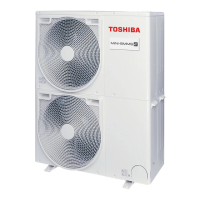
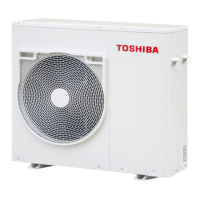
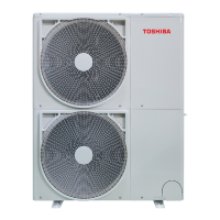
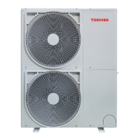
Details about the outdoor unit, including power supply and capacity.
Lists types of indoor units that can be connected to the outdoor unit.
Information on branching joints and headers used in the system.
Details about the PMV kit used in the air conditioner system.
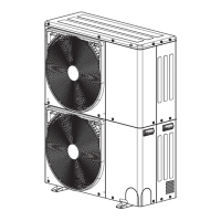
Diagrams illustrating the physical layout and dimensions of the outdoor unit.
Schematic showing electrical connections and components for the air conditioner system.
Specifications and ratings for various outdoor unit and inverter components.
Diagrams showing the physical arrangement of parts within the outdoor unit and inverter assembly.
Diagrams and connectivity for interface and inverter P.C. boards.
Important safety warnings related to the air conditioner unit operation and maintenance.
Essential safety guidelines to prevent injury and damage during installation, maintenance, and repair.
Safety and handling precautions specific to the R410A refrigerant.
Specifies pipes, materials, and tools suitable for the R410A refrigerant system.
Lists the necessary tools specifically for R410A refrigerant.
Lists general tools that can also be used with R410A systems.
Details about the outdoor unit, including power supply and capacity.
Lists types of indoor units that can be connected to the outdoor unit.
Information on branching joints and headers used in the system.
Details about the PMV kit used in the air conditioner system.
Specifications and ratings for the outdoor unit components.
Specifications and ratings for the outdoor inverter components.
Detailed diagram and connectivity of the interface P.C. board.
Details on the operation and control of the Pulse Motor Valve (PMV).
Explains the control logic for the outdoor fan speed during cooling operation.
Control logic for the outdoor fan speed during heating operation.
How the compressor capacity is controlled based on indoor demands.
Procedures for recovering refrigerant and oil during cooling and heating operations.
Details on the defrosting control mechanism and conditions.
Function of SV2 for achieving gas balance during compressor shutdown.
Control function of SV2 to mitigate pressure rise during low-speed compressor operation.
Function of SV2 to prevent rapid pressure fall during transient operation.
Control function of SV4 for low-pressure protection.
Function to correct compressor operation command and suppress high pressure rise.
Control of inverter input current to prevent exceeding specified values.
IGBT overheat protection based on TH sensor detection.
Protection mechanism against abnormal current detected by the IPDU P.C. board.
Control related to compressor case thermostat activation.
Control actions when the high pressure SW of an inverter compressor is activated.
Adjusts outdoor fan speed for duct installation with high static pressure.
Sets priority operation modes for better customer service.
Instructions for installing optional P.C. boards onto the interface P.C. board.
Enables outdoor fan operation based on snowfall detection.
Allows system start/stop control from the outdoor unit.
Reduces system capacity and noise during specific periods.
Controls the operating mode (cooling/heating) via switches or jumper wires.
How to change indoor unit operating modes using jumper wires.
Signals for system operation status and error occurrences.
Outlines the steps for performing a test operation on the system.
Verifies installation and wiring before initiating test operations.
Important precautions to follow before starting the address setup procedure.
Step-by-step guide for setting up and verifying unit addresses.
Procedure for setting addresses when controlling a single refrigerant line centrally.
Procedure for setting addresses when controlling multiple refrigerant lines centrally.
Troubleshooting steps when a check code appears on the remote controller.
Addresses issues when remote controller operations fail and check codes appear.
Troubleshoots lack of response and check codes on the outdoor unit's 7-segment display.
Procedure for checking the operation of the indoor unit fan.
Criteria for normal temperature differences in cooling and heating operations.
Guidelines for acceptable operating power current values for outdoor units.
Criteria for operating pressure and other cycle status indicators.
Steps to clear errors from the main remote controller and indoor units.
Procedures to clear errors using switches on the outdoor unit's interface P.C. board.
Method to clear errors by resetting power to all units.
Function to force PMV open or close for 2 minutes in indoor units.
Function to force PMV opening degree adjustment in the outdoor unit.
Provides an overview of troubleshooting procedures and necessary tools.
Explains how to use displays and check codes to identify faults.
Guides troubleshooting using information displayed on the remote controller.
Explains how to interpret symbols and data shown on displays.
Lists check codes and their corresponding locations and causes for troubleshooting.
Procedure for checking inverter output voltage to the compressor.
Method for checking compressor winding and earth resistances.
Procedure for checking the outdoor fan motor for faults and winding resistance.
Steps to check the 7-segment display following an abnormal unit shutdown.
How to display and interpret outdoor unit EEPROM error codes.
Resistance values for TS, TE, TL, and TO sensors at various temperatures.
Resistance values for the TD sensor at various temperatures.
Voltage and pressure data for the outdoor unit's Pd pressure sensor.
Voltage and pressure data for the outdoor unit's Ps pressure sensor.
Resistance values for the Indoor TA sensor at various temperatures.
Procedures for replacing common outdoor unit components like panels and motors.
Step-by-step guide for replacing the interface P.C. board.
Step-by-step guide for replacing the IPDU P.C. board.
Visual breakdown of the outdoor unit with a list of all parts and their references.
Guidelines for preventing refrigerant concentration from exceeding set limits in rooms.





 Loading...