EasyManua.ls Logo

Toshiba MMK-AP0241H User Manual

Toshiba MMK-AP0241H
91 pages
To Next Page IconTo Next Page
Page #1 background imageLoading...
Page #1 background image
R410A
FILE NO. A05-012
OWNER’S MANUAL
/
INSTALLATION MANUAL
Indoor Unit
<4-way Air Discharge Cassette Type>
MMU-AP0091H, AP0121H, AP0151H,
MMU-AP0181H, AP0241H, AP0271H,
MMU-AP0301H, AP0361H, AP0481H
MMU-AP0561H
<2-way Air Discharge Cassette Type>
MMU-AP0071WH, AP0091WH, AP0121WH,
MMU-AP0151WH, AP0181WH, AP0241WH,
MMU-AP0271WH, AP0301WH, AP0481WH*
* CHINA market only
<1-way Air Discharge Cassette Type>
MMU-AP0071YH, AP0091YH, AP0121YH,
MMU-AP0151SH, AP0181SH, AP0241SH,
MMU-AP0152SH, AP0182SH, AP0242SH
<Concealed Duct Standard Type>
MMD-AP0071BH, AP0091BH, AP0121BH, AP0151BH,
MMD-AP0181BH, AP0241BH, AP0271BH, AP0301BH,
MMD-AP0361BH, AP0481BH, AP0561BH
<Concealed Duct High Static Pressure Type>
MMD-AP0181H, AP0241H, AP0271H,
MMD-AP0361H, AP0481H
<Slim Duct Type>
MMD-AP0071SPH, AP0091SPH, AP0121SPH,
MMD-AP0151SPH, AP0181SPH
<Under Ceiling Type>
MMC-AP0151H, AP0181H, AP0241H,
MMC-AP0271H, AP0361H, AP0481H
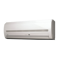
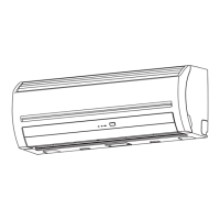
<High Wall Type>
MMK-AP0071H, AP0091H, AP0121H,
MMK-AP0151H, AP0181H, AP0241H,
MMK-AP0072H, AP0092H, AP0122H
<Floor Standing Cabinet Type>
MML-AP0071H, AP0091H, AP0121H,
MML-AP0151H, AP0181H, AP0241H
<Floor Standing Concealed Type>
MML-AP0071BH, AP0091BH, AP0121BH,
MML-AP0151BH, AP0181BH, AP0241BH
<Floor Standing Type>
MMF-AP0151H, AP0181H, AP0241H,AP0271H,
MMF-AP0361H, AP0481H, AP0561H
Outdoor Unit
<Inverter Unit>
MMY-MAP0802FT8
MMY-MAP1002FT8
MMY-MAP1202FT8
Heat Recovery Type
PRINTED IN JAPAN, Aug, 2005 ToMo
The indoor unit in Super Heat Recovery Multi System is common to one in Super Modular Multi System air conditioner.
Therefore refer to the service manuals for A03-009, A03-010, and A03-011 separately issued.
System air conditioner
Flow Selector Unit (FS unit)
RBM-Y1122FE
RBM-Y1802FE
RBM-Y2802FE

Other manuals for Toshiba MMK-AP0241H

Question and Answer IconNeed help?

Do you have a question about the Toshiba MMK-AP0241H and is the answer not in the manual?

Toshiba MMK-AP0241H Specifications

General IconGeneral
BrandToshiba
ModelMMK-AP0241H
CategoryAir Conditioner
LanguageEnglish

Summary

PRECAUTIONS FOR SAFETY

Warning on installation

Installation safety guidelines to prevent fire, electric shock, or injury.

Warning on use

Operational safety guidelines to prevent excessive cooling or injury from internal parts.

Warning on moving/repair

Safety guidelines for moving, re-installing, or repairing the air conditioner.

Caution on installation

Installation cautions regarding drainage, earthing, and flammable gas.

Check fixing method

Safety checks for installation, including earthing and secure fixing.

NAME OF EACH PART

Sold Separately Parts

Lists of additional components available separately.

PARTS NAME OF REMOTE CONTROLLER

Display section

Describes the various indicators and elements on the remote controller display.

CORRECT USAGE

Preparation

Initial setup steps before operating the air conditioner for the first time.

ADJUSTMENT OF WIND DIRECTION

How to set up the air direction

Instructions for adjusting airflow direction for cooling and heating.

How to start swinging

Procedure to initiate automatic airflow oscillation.

How to stop swinging

Procedure to halt automatic airflow oscillation.

TIMER OPERATION

Timer operation

Explains the selection and setup of OFF, Repeat OFF, and ON timers.

INSTALLATION

Installation location

Guidelines for selecting a suitable and safe installation site.

Electric wiring

Requirements and safety precautions for electrical connections.

MAINTENANCE

Cleaning of air filter

Procedure for cleaning air filters when indicated by the remote controller.

HINTS FOR ECONOMICAL OPERATION

Maintain room temperature at comfortable level

Advice on setting room temperature for comfort and efficiency.

Clean air filters

Emphasizes the importance of clean filters for optimal performance.

Never open doors and windows more often than necessary

Energy saving tip to maintain indoor temperature.

Window curtains

Using curtains to improve efficiency in cooling and heating.

Get uniform circulation of room air

Tips for managing airflow for even room temperature distribution.

AIR CONDITIONER OPERATIONS AND PERFORMANCE

Check before operation

Essential checks to perform before starting the air conditioner.

Defrost operation during heating operation

Explanation of the defrost mode during heating operation.

Protective device (High pressure switch)

Details on the high pressure switch safety feature.

Characteristics of heating operation

Information on heating performance and operational characteristics.

RE-INSTALLATION

Do not install the air conditioner in the following places

List of prohibited locations for air conditioner installation.

WHEN THE FOLLOWING SYMPTOMS ARE FOUND

Check the points described below before asking repair servicing.

Initial troubleshooting guidance for common symptoms.

Confirmation and check

Confirmation of error history

Procedure to check past error logs stored in the system.

ACCESSORY PARTS

Accessory parts

List of included accessory parts with specifications.

SAFETY CAUTION

1 INSTALLATION OF NEW REFRIGERANT AIR CONDITIONER

Required tools and cautions on handling

Tools and handling advice for installing new R410A refrigerant.

2 SELECTION OF INSTALLATION PLACE

Installation space

Required space for installation and service access.

3 OUTDOOR UNIT CARRYING IN

4 INSTALLATION OF OUTDOOR UNIT

Be careful to connecting arrangement of the header unit and the follower units.

Guidelines for arranging multiple outdoor units for proper connection.

5 REFRIGERANT PIPING

Connection of refrigerant pipe

Procedure for connecting refrigerant pipes to the unit.

5 REFRIGERANT PIPING

Pipe connecting method of valve (Example)

Examples and procedures for connecting valves in the refrigerant piping.

5 REFRIGERANT PIPING

Coupling size of brazed pipe

Specifications for brazed pipe coupling sizes.

Selection of pipe materials and size

Guidelines for selecting appropriate pipe materials and sizes.

5 REFRIGERANT PIPING

Selection of refrigerant piping

Details on selecting piping for various connection scenarios.

5 REFRIGERANT PIPING

Airtight test

Procedures for performing an airtight test on the refrigerant piping.

5 REFRIGERANT PIPING

Addition of refrigerant

Calculation and procedure for adding refrigerant.

5 REFRIGERANT PIPING

Full opening of valve

Instructions for fully opening the valves on the unit.

Heat insulation for pipe

Process for applying heat insulation to refrigerant pipes.

SAFETY CAUTION

6 ELECTRIC WORK

Electric wiring design

General design considerations for electrical wiring.

6 ELECTRIC WORK

Power supply specifications of combined outdoor units

Power supply wiring specifications for combined outdoor units.

6 ELECTRIC WORK

Unit capacities and power supply wire sizes (Reference)

Reference table for unit capacities and corresponding wire sizes.

6 ELECTRIC WORK

Specifications of wires for controlling

Specifications for control wiring between units.

Group Control through a Remote Controller

Setup for group control of multiple indoor units via remote controller.

6 ELECTRIC WORK

Power supply specifications of outdoor unit

Specifications for the outdoor unit's power supply.

6 ELECTRIC WORK

Connection of power supply wire with control wire

Procedure for connecting power and control wires.

6 ELECTRIC WORK

Power supply wire

Details on the power supply wiring.

Control wire

Details on the control wiring.

6 ELECTRIC WORK

System wiring diagram

Overall schematic of the system wiring connections.

6 ELECTRIC WORK

Connection of power supply wire with control wire

Detailed procedure for connecting power and control wires.

7 ADDRESS SETUP

Set up address after wiring work.

Initial address setup procedure after wiring is completed.

Automatic Address Setup

Procedure for automatic configuration of unit addresses.

7 ADDRESS SETUP

Address setup procedure 1

Steps for automatic address setup.

Address setup procedure 2

Steps for address setup with central control.

7 ADDRESS SETUP

Switch setup

Procedure for setting addresses using switches on the P.C. board.

7 ADDRESS SETUP

Manual address setup from remote controller

Procedure for setting unit addresses using the wired remote controller.

7 ADDRESS SETUP

Confirmation of indoor address and the main unit position on the remote controller

Procedure to check indoor unit addresses and positions on the remote.

7 ADDRESS SETUP

Confirmation of indoor address and the main unit position on the remote controller

Procedure to check indoor unit addresses and positions on the remote.

7 ADDRESS SETUP

Change of indoor address from wired remote controller

Procedure to modify indoor unit addresses via remote controller.

7 ADDRESS SETUP

To change all the indoor addresses from an arbitrary wired remote controller

Procedure for changing all indoor unit addresses from any wired remote.

7 ADDRESS SETUP

Clearance of address (Return to status (Address undecided) at shipment from factory)

Procedure to reset unit addresses to factory default status.

8 SETTING WHEN CONNECTING MULTIPLE INDOOR UNITS TO A FS UNIT

Cautions to connection of indoor unit

Precautions when connecting multiple indoor units to a single FS unit.

Incorrect example of connection

Illustrates improper connection examples for multiple indoor units.

How to set up Item code

Procedure for setting the Item code when connecting multiple units.

9 HOW TO SET UP THE COOLING ONLY INDOOR UNIT

10 TEST OPERATION

Before test operation

Essential checks before performing a test operation.

How to perform a test operation

Procedure for conducting a test operation using the remote controller.

10 TEST OPERATION

In case of test operation on the interface P.C. board of the outdoor unit

Procedure for performing test operation via the outdoor unit's P.C. board.

11 TROUBLESHOOTING

Segment display and check code

Diagnosing issues using segment display and check codes.

Check Code (Outdoor 7-segment display [B])

Details of outdoor unit error codes indicated on the 7-segment display.

11 TROUBLESHOOTING

Check Code (Outdoor 7-segment display [B])

Details of outdoor unit error codes indicated on the 7-segment display.

Accessory parts and Parts to be procured Locally

Accessory parts

List of included accessory parts with specifications.

2 INSTALLATION OF NEW REFRIGERANT AIR CONDITIONER

Required tools and cautions on handling

Tools and handling advice for installing new R410A refrigerant.

3 SELECTION OF INSTALLATION PLACE

Installation space

Space requirements for installation and service access.

4 INATALLATION OF FLOW SELECTOR UNIT

Installing hanging bolts

Procedures for installing hanging bolts for the unit.

5 REFRIGERANT PIPING

Permissible pipe length and permissible height difference

Pipe length and height limits for refrigerant lines.

5 REFRIGERANT PIPING

One indoor unit connection

Piping specifications for connecting a single indoor unit.

5 REFRIGERANT PIPING

Pipe forming/End positioning

Instructions for pipe flaring and end positioning.

5 REFRIGERANT PIPING

Airtight test/Air purge, etc.

Procedures for airtight testing, air purging, and leak checks.

Gas leak check

Methods for checking refrigerant gas leaks.

Heat insulating process

Process for applying heat insulation to refrigerant pipes.

6 ELECTRIC WORK

Indoor unit

Wiring instructions specific to the indoor unit.

6 ELECTRIC WORK

Connections

Wiring connection details for indoor units.

6 ELECTRIC WORK

6 ELECTRIC WORK

6 ELECTRIC WORK

6 ELECTRIC WORK

6 ELECTRIC WORK

6 ELECTRIC WORK

6 ELECTRIC WORK

6 ELECTRIC WORK

Setting when connecting multiple indoor units to a FS unit

Cautions to connection of indoor unit

Precautions when connecting multiple indoor units to a FS unit.

Incorrect example of connection

Illustrates improper connection examples for multiple indoor units.

How to set up Item code

Procedure for setting the Item code when connecting multiple units.

WARNINGS ON REFRIGERANT LEAKAGE

Check of Concentration Limit

Information on refrigerant concentration limits in installation rooms.

Related product manuals