Do you have a question about the Toshiba MMU-AP0481H and is the answer not in the manual?
Installation work requires specialized knowledge; self-installation may cause hazards.
Avoid prolonged direct exposure to cool air; do not insert objects into air inlets/outlets.
Never modify the unit; leave repairs to qualified personnel to prevent electric shock or fire.
Ensure proper drain piping, earthing, and installation away from flammable gases.
Verify installation plate is undamaged; avoid placing combustible items or water near the unit.
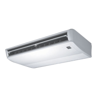
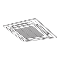
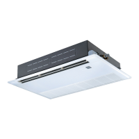
Details and diagrams of various indoor unit types and their components.
Images and names of remote controllers available for separate purchase.
Explanation of indicators and displays on the remote controller's screen.
Details of buttons used for operating the air conditioner and their functions.
Steps to take before using the air conditioner for the first time or after changing settings.
Essential conditions for operating the air conditioner, including power switch usage.
Recommendation for horizontal louvers during cooling to prevent dew formation.
Specific instructions for adjusting air direction for 4-way cassette units during cooling and heating.
Explanation of different timer types: OFF, Repeat OFF, and ON timers.
Guidelines and warnings for selecting a suitable installation site.
Safety warnings and requirements for proper electrical wiring and grounding.
Instructions and warnings regarding air filter cleaning and maintenance.
Essential checks to perform before operating the air conditioner.
Factors affecting heating performance, especially at low outdoor temperatures.
How the high pressure switch protects the unit from excessive load.
Recommended outdoor and room temperature ranges for optimal cooling performance.
Recommended outdoor and room temperature ranges for optimal heating performance.
Warnings about potential electric shock or fire if the unit is reinstalled improperly.
Procedure to check past trouble codes and their history on the remote controller.
List of included accessory parts with their quantities and shapes.
Important safety cautions to be observed during installation and use.
Critical warnings regarding installation, refrigerant handling, and electrical work.
List of necessary tools and precautions for installing R410A systems.
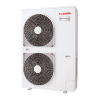
Recommended clearances and space requirements for outdoor unit installation and servicing.
Table showing outdoor unit model combinations based on equivalent HP.
Instructions for safely loading, unloading, and transporting the outdoor unit.
Guidance on installing the outdoor unit in a place with good drainage, considering snowfall.
Steps and requirements for connecting refrigerant pipes, including brazing with nitrogen.
Examples of connecting pipes and valves for different outdoor unit models.
Diagrams and guidelines for designing the electrical wiring for combined outdoor units.
Specifications for selecting power supply and control wires for indoor and outdoor units.
Guide to manually set indoor unit addresses via the wired remote controller.
Procedure to reset indoor unit addresses to factory default.
Steps for configuring the Item code after address setup for multiple indoor units.
Step-by-step guide to set an indoor unit to Cooling Only mode without using a flow selector.
Checks to perform before starting a test operation, including valve status and earth resistance.
Instructions for conducting a test operation using the wired remote controller.
Performing test operations using switches on the outdoor unit's interface P.C. board.
Using the outdoor unit's 7-segment display and DIP switches for diagnosing problems.
Table listing outdoor unit check codes and their meanings for troubleshooting.
List of accessory parts, quantities, and shapes for different models.
Ensuring compliance with local, national, and international safety regulations.
Details on piping materials and dimensions for R410A refrigerant systems.
Lists locations to avoid for installation to prevent malfunctions or hazards.
Diagrams showing the external dimensions and connection ports of the Flow Selector unit.
Steps for installing hanging bolts and preparing the ceiling for the Flow Selector unit.
Specifications for seamless phosphorus deoxidized copper pipes for air conditioning connections.
Instructions for wiring connections within the indoor unit for power supply and control.
Configuration steps for multiple indoor units connected to a single FS unit.
| Brand | Toshiba |
|---|---|
| Model | MMU-AP0481H |
| Category | Air Conditioner |
| Language | English |