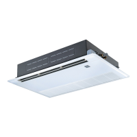
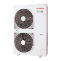
How to clean a contaminated filter in a Toshiba MMU-AP0482H Air Conditioner?
- JJason SmithAug 12, 2025
If the filter of your Toshiba Air Conditioner is contaminated, wash it with water to remove the contamination.

How to clean a contaminated filter in a Toshiba MMU-AP0482H Air Conditioner?
If the filter of your Toshiba Air Conditioner is contaminated, wash it with water to remove the contamination.
What to do if the filter of my Toshiba Air Conditioner is damaged?
If the filter of your Toshiba Air Conditioner is damaged, replace it with a new one.
What to do if there is dust/dirt clogging in the drain pan of my Toshiba MMU-AP0482H?
If the drain pan of your Toshiba Air Conditioner is clogged with dust or dirt, clean the drain pan. Also, make sure to check the downward slope to ensure smooth drainage.
How to clean dust/dirt clogging in the heat exchanger of Toshiba MMU-AP0482H Air Conditioner?
If the heat exchanger in your Toshiba Air Conditioner is clogged with dust or dirt, wash it to remove the blockage.
How to clean a contaminated fan in a Toshiba MMU-AP0482H?
If the fan of your Toshiba Air Conditioner is contaminated, brush or wash it to remove the contamination.
What to do if ornamental panel or louvers of Toshiba MMU-AP0482H are contaminated?
If the ornamental panel or louvers of your Toshiba Air Conditioner are contaminated, wash them. Alternatively, you can apply a repair coating.
What to do if air inlet/outlet grilles of my Toshiba MMU-AP0482H are deformed or damaged?
If the air inlet or outlet grilles of your Toshiba Air Conditioner are deformed or damaged, fix or replace them.
What to do if Toshiba Air Conditioner fan has vibration or balance issues?
If the fan of your Toshiba Air Conditioner has terrible vibration or balance issues, replace it.
| Brand | Toshiba |
|---|---|
| Model | MMU-AP0482H |
| Category | Air Conditioner |
| Language | English |
Safety precautions for R410A refrigerant.
Important notes for installation and service with R410A.
Recommended materials for refrigerant pipes.
Tools specifically required for R410A refrigerant handling.
Common tools usable for R410A and conventional refrigerants.
Detailed specifications for the indoor unit models.
External dimensions and construction details for specific models.
Wiring diagram for the 4-way air discharge cassette type.
Ratings and specifications for various unit parts.
Identification and description of key unit components.
Explanation of indicators and sections on the remote controller display.
Description of buttons and functions on the remote controller.
Information on using the remote controller sensor.
General guidelines for adjusting wind direction.
Specific wind direction adjustments for ceiling/wall types.
Wind direction settings for 1H series and compact models.
Wind direction settings for 2H series models.
Guidelines for selecting a suitable installation location.
Safety measures for electrical wiring during installation.
Routine maintenance tasks for the unit.
Procedure for cleaning the air filters.
Procedures for cleaning unit panels and filters.
Steps to detach and clean the discharge louver.
Pre-operation checks to ensure proper functioning.
Recommended temperature and humidity ranges for operation.
Procedure to check past error records.
List of included and separately sold accessory parts.
Critical safety instructions for installation.
Visual guide to external dimensions and hanging bolt setup.
Procedures for ceiling opening and installing hanging bolts.
Considerations for ceiling structure during installation.
Details on selecting and installing hanging bolts.
Requirements for drain pipe material and heat insulation.
Steps for connecting drain pipes and checking drainage.
Guidelines for refrigerant piping and flare nut connections.
Limits for piping length and height between units.
Specifications for pipe sizes and flaring techniques.
Details on power supply and communication wire specifications.
Proper torque values for tightening pipe connections.
Procedures for modifying unit settings via remote controller.
Pre-test run checks and power supply requirements.
Step-by-step guide for performing test runs.
Instructions for cleaning the air filters.
Procedures for cleaning unit panels and filters.
Steps to detach and clean the discharge louver.
Methods for confirming and checking unit status and errors.
Procedure to review past error records.
Detailed specifications for unit control functions.
Block diagram of the indoor unit control circuit.
Diagram showing wired remote controller connections.
Procedure for performing cooling and heating test runs.
Procedures for configuring indoor unit functions via wired remote.
Preliminary checks and required tools before troubleshooting.
Step-by-step guide for diagnosing and resolving issues.
Using remote controller display for troubleshooting.
Reviewing past error records on the remote controller.
Procedures for removing and installing the suction grille.
Steps for removing and installing the electric parts cover.
Detailed steps for replacing the indoor unit's P.C. board.
Visual breakdown and parts list for specific indoor unit models.


 Loading...