EasyManua.ls Logo

Toshiba MMU-UP0121HP-E User Manual

Toshiba MMU-UP0121HP-E
295 pages
To Next Page IconTo Next Page
Page #1 background imageLoading...
Page #1 background image
AIR CONDITIONER (MULTI TYPE)
SERVICE MANUAL
Indoor unit
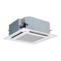
<4-way cassette type>
MMU-UP0091HP-E(TR)
MMU-UP0121HP-E(TR)
MMU-UP0151HP-E(TR)
MMU-UP0181HP-E(TR)
MMU-UP0241HP-E(TR)
MMU-UP0271HP-E(TR)
MMU-UP0301HP-E(TR)
MMU-UP0361HP-E(TR)
MMU-UP0481HP-E(TR)
MMU-UP0561HP-E(TR)
<Ceiling type>
MMC-UP0151HP-E(TR)
MMC-UP0181HP-E(TR)
MMC-UP0241HP-E(TR)
MMC-UP0271HP-E(TR)
MMC-UP0361HP-E(TR)
MMC-UP0481HP-E(TR)
MMC-UP0561HP-E(TR)
<Concealed Duct Standard type>
MMD-UP0051BHP-E
MMD-UP0071BHP-E(TR)
MMD-UP0091BHP-E(TR)
MMD-UP0121BHP-E(TR)
MMD-UP0151BHP-E(TR)
MMD-UP0181BHP-E(TR)
MMD-UP0241BHP-E(TR)
MMD-UP0271BHP-E(TR)
MMD-UP0301BHP-E(TR)
MMD-UP0361BHP-E(TR)
MMD-UP0481BHP-E(TR)
MMD-UP0561BHP-E(TR)
<Concealed Duct High Static Pressure type>
MMD-UP0181HP-E(TR)
MMD-UP0241HP-E(TR)
MMD-UP0271HP-E(TR)
MMD-UP0361HP-E(TR)
MMD-UP0481HP-E(TR)
MMD-UP0561HP-E(TR)
MMD-UP0721HP-E(TR)
MMD-UP0961HP-E(TR)
<Concealed Duct High Static Pressure
fresh air intake type>
MMD-UP0481HFP-E(TR)
MMD-UP0721HFP-E(TR)
MMD-UP0961HFP-E(TR)
MMD-UP1121HFP-E(TR)
MMD-UP1281HFP-E(TR)
<Console type>
MML-UP0071NHP-E(TR)
MML-UP0091NHP-E(TR)
MML-UP0121NHP-E(TR)
MML-UP0151NHP-E(TR)
MML-UP0181NHP-E(TR)
<High wall type>
MMK-UP0031HP-E(TR)
MMK-UP0051HP-E(TR)
MMK-UP0071HP-E(TR)
MMK-UP0091HP-E(TR)
MMK-UP0121HP-E(TR)
MMK-UP0151HP-E(TR)
MMK-UP0181HP-E(TR)
MMK-UP0241HP-E(TR)
MMK-UP0031HPL-E(TR)
MMK-UP0051HPL-E(TR)
MMK-UP0071HPL-E(TR)
MMK-UP0091HPL-E(TR)
MMK-UP0121HPL-E(TR)
MMK-UP0151HPL-E(TR)
MMK-UP0181HPL-E(TR)
MMK-UP0241HPL-E(TR)
FILE NO. SVM-20095
January, 2021

Table of Contents

Other manuals for Toshiba MMU-UP0121HP-E

Questions and Answers:

Toshiba MMU-UP0121HP-E Specifications

General IconGeneral
BrandToshiba
ModelMMU-UP0121HP-E
CategoryAir Conditioner
LanguageEnglish

Summary

Warning Indications on the Air Conditioner Unit

Confirmation of warning label on the main unit

Instructs to confirm the presence and position of warning labels on the main unit for safe operation.

PRECAUTIONS FOR SAFETY

Definition of Qualified Installer or Qualified Service Person

Defines the qualifications and knowledge required for air conditioner installation and service personnel.

Definition of Protective Gear

Lists required protective gear for various tasks and explains safety indications and marks.

1. SPECIFICATIONS

1-1. 4-way cassette type

Provides detailed technical specifications for 4-way cassette indoor units, including capacity, sound levels, and weight.

1-2. Ceiling type

Lists specifications for ceiling type indoor units, covering performance, dimensions, and electrical characteristics.

1-3. Concealed Duct Standard type

Outlines specifications for concealed duct standard units, including performance data and physical dimensions.

1-4. Concealed Duct High Static Pressure type

Provides technical specifications for high static pressure concealed duct units, detailing performance and physical attributes.

1-5. Concealed Duct High Static Pressure fresh air intake type

Details specifications for concealed duct units with fresh air intake, covering performance and dimensions.

1-6. Console type

Lists specifications for console type indoor units, including performance metrics and physical dimensions.

1-7. High wall type

Provides technical specifications for high wall type indoor units, covering performance, dimensions, and electrical data.

2. CONSTRUCTION VIEWS (EXTERNAL VIEWS)

2-1. 4-way cassette type

Presents external views and dimensions for 4-way cassette indoor units, illustrating installation requirements.

2-2. Ceiling type

Shows external views and dimensions for ceiling type indoor units, detailing installation clearances and component locations.

2-3. Concealed Duct Standard type

Provides external views and dimensions for concealed duct standard units, essential for installation planning.

2-4. Concealed Duct High Static Pressure type

Illustrates external views and dimensions for high static pressure concealed duct units, crucial for installation.

2-5. Concealed Duct High Static Pressure fresh air intake type

Displays external views and dimensions for concealed duct units with fresh air intake, vital for installation.

2-6. Console type

Presents external views and dimensions for console type indoor units, detailing installation and mounting.

2-7. High wall type

Shows external views and dimensions for high wall type indoor units, important for installation and access.

3. WIRING DIAGRAMS

3-1. 4-way cassette type

Illustrates the wiring diagram for 4-way cassette type indoor units, detailing electrical connections.

3-2. Ceiling type

Provides the wiring diagram for ceiling type indoor units, showing electrical connections and component layout.

3-3. Concealed Duct Standard type

Details the wiring diagram for concealed duct standard type units, essential for troubleshooting.

3-4. Concealed Duct High Static Pressure type

Presents the wiring diagram for high static pressure concealed duct units, crucial for diagnosis.

3-5. Concealed Duct High Static Pressure fresh air intake type

Shows the wiring diagram for concealed duct units with fresh air intake, vital for understanding connections.

3-6. Console type

Illustrates the wiring diagram for console type indoor units, detailing electrical connections.

3-7. High wall type

Provides the wiring diagram for high wall type indoor units, essential for electrical configurations.

4. PARTS RATING

Indoor unit

Lists parts rating for various indoor unit types, including fan motors, sensors, and PC boards.

5. REFRIGERANT CYCLE DIAGRAM

Explanation of functional parts in indoor unit

Explains the function of key components in the indoor unit's refrigerant cycle, including sensors and valves.

6. CONTROL OUTLINE

Control Specifications

Outlines control specifications, detailing operation modes, fan speed selection, and temperature settings.

7. COMMUNICATION TYPE, MODEL NAMES AND THE MAXIMUM NUMBER OF CONNECTABLE UNITS

7-1. Communication specifications and model names

Details communication types (TU2C-Link, TCC-Link) and lists compatible model names and controllers.

7-2. Unit combination and connectable units

Explains unit combinations and maximum connectable indoor units for different communication types, crucial for system design.

8. APPLIED CONTROL AND FUNCTIONS (INCLUDING CIRCUIT CONFIGURATION)

8-1. Indoor controller block diagram (MCC-1643)

Shows the block diagram for the MCC-1643 indoor controller, illustrating connections for wired remote controllers.

8-2. Indoor controller block diagram (MCC-1720)

Provides the block diagram for the MCC-1720 indoor controller, detailing connections for remote controllers.

8-3. Indoor controller block diagram (MCC-1696)

Illustrates the block diagram for the MCC-1696 indoor controller, showing connections for various control inputs.

8-4. Indoor Print Circuit Board

Details the layout and components of the indoor unit's print circuit boards for servicing purposes.

8-5. Test run of indoor unit

Describes the procedure for performing a test run to check cooling/heating operation and ensure proper function.

8-6. Method to set indoor unit function DN code

Explains how to set indoor unit function codes (DN codes) using a wired remote controller for customization.

8-7. Applied control of indoor unit

Details applied control methods, including ON/OFF control and ventilation fan control from the remote controller.

9. TROUBLESHOOTING

9-1. Overview

Provides an overview of troubleshooting, applicable models, required tools, and normal behaviors.

9-2. Troubleshooting method

Explains how to identify trouble sites using check codes displayed on remote controllers and outdoor units.

9-3. Troubleshooting based on information displayed on remote controller

Guides users on troubleshooting based on check codes and trouble history displayed on the remote controller.

9-4. Check Codes Displayed on Remote Controller and SMMS series Outdoor Unit (7-Segment Display on I/F Board) and Locations to Be Checked

Lists check codes, their detection conditions, and potential locations for checking to diagnose issues.

9-5. Diagnostic Procedure for Each Check Code (Indoor Unit)

Provides step-by-step diagnostic procedures for indoor unit check codes, aiding in problem resolution.

9-6. Sensor characteristics

Details the resistance characteristics of indoor unit sensors (TA, TC1, TC2, TCJ) across temperature ranges for troubleshooting.

9-7. Maintenance list

Outlines recommended maintenance procedures for indoor and outdoor units, including cleaning and inspection schedules.

10. P.C. BOARD EXCHANGE PROCEDURES

10-1. Replacement of indoor P.C. boards

Provides procedures for replacing the indoor unit's P.C. board, including EEPROM data handling.

11. DETACHMENTS

11-1. 4-way cassette type

Details detachment and attachment procedures for 4-way cassette indoor unit components like grilles and covers.

11-2. Ceiling type

Describes detachment and attachment procedures for ceiling type indoor unit components, such as air intake grilles and electric parts boxes.

11-3. Concealed Duct Standard type

Outlines detachment and attachment procedures for concealed duct standard units, focusing on air filters and panels.

11-4. Concealed Duct High Static Pressure type

Provides detachment and attachment procedures for high static pressure concealed duct units, covering panels and PC boards.

11-5. Concealed Duct High Static Pressure fresh air intake type

Details detachment and attachment procedures for concealed duct units with fresh air intake, including panels and PC boards.

11-6. Console type

Explains detachment and attachment procedures for console type indoor units, focusing on front panels and electric parts assemblies.

11-7. High wall type

Describes detachment and attachment procedures for high wall type indoor units, covering air inlet grilles and air filters.

12. EXPLODED VIEWS AND PARTS LIST

12-1. 4-way cassette type

Provides an exploded view and parts list for 4-way cassette indoor units, identifying components by number.

12-2. Ceiling type

Shows an exploded view and parts list for ceiling type indoor units, detailing component identification.

12-3. Concealed Duct Standard type

Presents an exploded view and parts list for concealed duct standard units, aiding in part identification.

12-4. Concealed Duct High Static Pressure type

Displays an exploded view and parts list for high static pressure concealed duct units, crucial for ordering.

12-5. Concealed Duct High Static Pressure fresh air intake type

Provides an exploded view and parts list for concealed duct units with fresh air intake, facilitating part identification.

12-6. Console type

Shows an exploded view and parts list for console type indoor units, helping to identify and order parts.

12-7. High wall type

Presents an exploded view and parts list for high wall type indoor units, essential for component identification.

Declaration of Conformity

Manufacturer Information

Provides details about the manufacturer, TOSHIBA CARRIER (THAILAND) CO., LTD., and their European counterpart.

Machinery Compliance

States compliance with the Machinery Directive (2006/42/EC) and harmonized standards like EN 378-2.

Related product manuals