EasyManua.ls Logo

Toshiba MMU-UP0271HP-E User Manual

Toshiba MMU-UP0271HP-E
295 pages
To Next Page IconTo Next Page
Page #1 background imageLoading...
Page #1 background image
AIR CONDITIONER (MULTI TYPE)
SERVICE MANUAL
Indoor unit
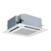
<4-way cassette type>
MMU-UP0091HP-E(TR)
MMU-UP0121HP-E(TR)
MMU-UP0151HP-E(TR)
MMU-UP0181HP-E(TR)
MMU-UP0241HP-E(TR)
MMU-UP0271HP-E(TR)
MMU-UP0301HP-E(TR)
MMU-UP0361HP-E(TR)
MMU-UP0481HP-E(TR)
MMU-UP0561HP-E(TR)
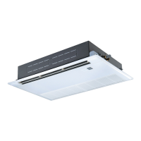
<Ceiling type>
MMC-UP0151HP-E(TR)
MMC-UP0181HP-E(TR)
MMC-UP0241HP-E(TR)
MMC-UP0271HP-E(TR)
MMC-UP0361HP-E(TR)
MMC-UP0481HP-E(TR)
MMC-UP0561HP-E(TR)
<Concealed Duct Standard type>
MMD-UP0051BHP-E
MMD-UP0071BHP-E(TR)
MMD-UP0091BHP-E(TR)
MMD-UP0121BHP-E(TR)
MMD-UP0151BHP-E(TR)
MMD-UP0181BHP-E(TR)
MMD-UP0241BHP-E(TR)
MMD-UP0271BHP-E(TR)
MMD-UP0301BHP-E(TR)
MMD-UP0361BHP-E(TR)
MMD-UP0481BHP-E(TR)
MMD-UP0561BHP-E(TR)
<Concealed Duct High Static Pressure type>
MMD-UP0181HP-E(TR)
MMD-UP0241HP-E(TR)
MMD-UP0271HP-E(TR)
MMD-UP0361HP-E(TR)
MMD-UP0481HP-E(TR)
MMD-UP0561HP-E(TR)
MMD-UP0721HP-E(TR)
MMD-UP0961HP-E(TR)
<Concealed Duct High Static Pressure
fresh air intake type>
MMD-UP0481HFP-E(TR)
MMD-UP0721HFP-E(TR)
MMD-UP0961HFP-E(TR)
MMD-UP1121HFP-E(TR)
MMD-UP1281HFP-E(TR)
<Console type>
MML-UP0071NHP-E(TR)
MML-UP0091NHP-E(TR)
MML-UP0121NHP-E(TR)
MML-UP0151NHP-E(TR)
MML-UP0181NHP-E(TR)
<High wall type>
MMK-UP0031HP-E(TR)
MMK-UP0051HP-E(TR)
MMK-UP0071HP-E(TR)
MMK-UP0091HP-E(TR)
MMK-UP0121HP-E(TR)
MMK-UP0151HP-E(TR)
MMK-UP0181HP-E(TR)
MMK-UP0241HP-E(TR)
MMK-UP0031HPL-E(TR)
MMK-UP0051HPL-E(TR)
MMK-UP0071HPL-E(TR)
MMK-UP0091HPL-E(TR)
MMK-UP0121HPL-E(TR)
MMK-UP0151HPL-E(TR)
MMK-UP0181HPL-E(TR)
MMK-UP0241HPL-E(TR)
FILE NO. SVM-20095
January, 2021

Table of Contents

Other manuals for Toshiba MMU-UP0271HP-E

Questions and Answers:

Toshiba MMU-UP0271HP-E Specifications

General IconGeneral
BrandToshiba
ModelMMU-UP0271HP-E
CategoryAir Conditioner
LanguageEnglish

Summary

PRECAUTIONS FOR SAFETY

1. SPECIFICATIONS

1-1. 4-way cassette type

Detailed specifications for 4-way cassette indoor units, including capacity, electrical characteristics, dimensions, and sound levels.

1-2. Ceiling type

Detailed specifications for ceiling-type indoor units, covering capacity, electrical characteristics, dimensions, and sound levels.

6. CONTROL OUTLINE

8. APPLIED CONTROL AND FUNCTIONS (INCLUDING CIRCUIT CONFIGURATION)

8-1. Indoor controller block diagram (MCC-1643)

Illustrates the internal block diagram of the MCC-1643 indoor controller for various connection scenarios.

8-2. Indoor controller block diagram (MCC-1720)

Shows the block diagram for the MCC-1720 indoor controller in different connection configurations.

8-3. Indoor controller block diagram (MCC-1696)

Presents the block diagram for the MCC-1696 indoor controller, detailing wired remote controller connections.

8-4. Indoor Print Circuit Board

Detailed view and component identification of the indoor print circuit boards (MCC-1643, MCC-1720, MCC-1696).

8-5. Test run of indoor unit

Procedure for performing cooling/heating test runs for indoor units using wired or wireless remote controllers.

8-6. Method to set indoor unit function DN code

Step-by-step guide for setting indoor unit functions using DN codes via wired remote controller.

8-7. Applied control of indoor unit

Explains control systems, including remote ON/OFF control box wiring and ventilation fan control.

9. TROUBLESHOOTING

9-1. Overview

General information on troubleshooting, applicable models, required tools, and normal behaviors.

9-2. Troubleshooting method

Detailed guide to identifying trouble sites using check codes from remote controllers, central control, and outdoor units.

9-3. Troubleshooting based on information displayed on remote controller

Procedure for checking trouble history and interpreting information displayed on the remote controller.

9-4. Check Codes Displayed on Remote Controller and SMMS series Outdoor Unit (7-Segment Display on I/F Board) and Locations to Be Checked

Lists check codes detected by various devices and their corresponding troubleshooting steps and locations.

9-5. Diagnostic Procedure for Each Check Code (Indoor Unit)

Flowcharts for diagnosing specific check codes related to indoor unit communication and sensor issues.

10. P.C. BOARD EXCHANGE PROCEDURES

10-1. Replacement of indoor P.C. boards

Procedure for replacing the indoor unit P.C. board, including EEPROM data handling for serviced units.

Related product manuals