EasyManua.ls Logo

Toshiba MMU-UP0091HP-E User Manual

Toshiba MMU-UP0091HP-E
295 pages
To Next Page IconTo Next Page
Page #1 background imageLoading...
Page #1 background image
AIR CONDITIONER (MULTI TYPE)
SERVICE MANUAL
Indoor unit
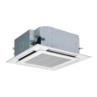
<4-way cassette type>
MMU-UP0091HP-E(TR)
MMU-UP0121HP-E(TR)
MMU-UP0151HP-E(TR)
MMU-UP0181HP-E(TR)
MMU-UP0241HP-E(TR)
MMU-UP0271HP-E(TR)
MMU-UP0301HP-E(TR)
MMU-UP0361HP-E(TR)
MMU-UP0481HP-E(TR)
MMU-UP0561HP-E(TR)
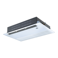
<Ceiling type>
MMC-UP0151HP-E(TR)
MMC-UP0181HP-E(TR)
MMC-UP0241HP-E(TR)
MMC-UP0271HP-E(TR)
MMC-UP0361HP-E(TR)
MMC-UP0481HP-E(TR)
MMC-UP0561HP-E(TR)
<Concealed Duct Standard type>
MMD-UP0051BHP-E
MMD-UP0071BHP-E(TR)
MMD-UP0091BHP-E(TR)
MMD-UP0121BHP-E(TR)
MMD-UP0151BHP-E(TR)
MMD-UP0181BHP-E(TR)
MMD-UP0241BHP-E(TR)
MMD-UP0271BHP-E(TR)
MMD-UP0301BHP-E(TR)
MMD-UP0361BHP-E(TR)
MMD-UP0481BHP-E(TR)
MMD-UP0561BHP-E(TR)
<Concealed Duct High Static Pressure type>
MMD-UP0181HP-E(TR)
MMD-UP0241HP-E(TR)
MMD-UP0271HP-E(TR)
MMD-UP0361HP-E(TR)
MMD-UP0481HP-E(TR)
MMD-UP0561HP-E(TR)
MMD-UP0721HP-E(TR)
MMD-UP0961HP-E(TR)
<Concealed Duct High Static Pressure
fresh air intake type>
MMD-UP0481HFP-E(TR)
MMD-UP0721HFP-E(TR)
MMD-UP0961HFP-E(TR)
MMD-UP1121HFP-E(TR)
MMD-UP1281HFP-E(TR)
<Console type>
MML-UP0071NHP-E(TR)
MML-UP0091NHP-E(TR)
MML-UP0121NHP-E(TR)
MML-UP0151NHP-E(TR)
MML-UP0181NHP-E(TR)
<High wall type>
MMK-UP0031HP-E(TR)
MMK-UP0051HP-E(TR)
MMK-UP0071HP-E(TR)
MMK-UP0091HP-E(TR)
MMK-UP0121HP-E(TR)
MMK-UP0151HP-E(TR)
MMK-UP0181HP-E(TR)
MMK-UP0241HP-E(TR)
MMK-UP0031HPL-E(TR)
MMK-UP0051HPL-E(TR)
MMK-UP0071HPL-E(TR)
MMK-UP0091HPL-E(TR)
MMK-UP0121HPL-E(TR)
MMK-UP0151HPL-E(TR)
MMK-UP0181HPL-E(TR)
MMK-UP0241HPL-E(TR)
FILE NO. SVM-20095
January, 2021

Table of Contents

Other manuals for Toshiba MMU-UP0091HP-E

Questions and Answers:

Toshiba MMU-UP0091HP-E Specifications

General IconGeneral
CategoryAir Conditioner
Power Supply220-240V, 50Hz
Energy Efficiency Ratio (Cooling)3.21
Coefficient of Performance (Heating)3.61
RefrigerantR410A
TypeSplit
Outdoor Unit Weight25 kg

Summary

SERVICE MANUAL

4-way Cassette Type

Lists models for the 4-way cassette type indoor unit.

Ceiling Type

Lists models for the ceiling type indoor unit.

Concealed Duct Standard Type

Lists models for the concealed duct standard type indoor unit.

Concealed Duct High Static Pressure Type

Lists models for the concealed duct high static pressure type indoor unit.

1. SPECIFICATIONS

1-1. 4-way Cassette Type Specifications

Detailed specifications for the 4-way cassette type indoor unit.

1-2. Ceiling Type Specifications

Detailed specifications for the ceiling type indoor unit.

1-3. Concealed Duct Standard Type Specifications

Detailed specifications for the concealed duct standard type indoor unit.

1-4. Concealed Duct High Static Pressure Type Specifications

Detailed specifications for the concealed duct high static pressure type indoor unit.

1-5. Concealed Duct High Static Pressure Fresh Air Intake Type Specifications

Detailed specifications for the concealed duct high static pressure fresh air intake type indoor unit.

1-6. Console Type Specifications

Detailed specifications for the console type indoor unit.

1-7. High Wall Type Specifications

Detailed specifications for the high wall type indoor unit.

2. CONSTRUCTION VIEWS (EXTERNAL VIEWS)

2-1. 4-way Cassette Type Views

Exploded views and dimensional drawings for the 4-way cassette type indoor units.

2-2. Ceiling Type Views

Exploded views and dimensional drawings for the ceiling type indoor units.

2-3. Concealed Duct Standard Type Views

Exploded views and dimensional drawings for the concealed duct standard type indoor units.

2-4. Concealed Duct High Static Pressure Type Views

Exploded views and dimensional drawings for the concealed duct high static pressure type indoor units.

2-5. Concealed Duct High Static Pressure Fresh Air Intake Type Views

Exploded views and dimensional drawings for the concealed duct high static pressure fresh air intake type indoor units.

2-6. Console Type Views

Exploded views and dimensional drawings for the console type indoor units.

2-7. High Wall Type Views

Exploded views and dimensional drawings for the high wall type indoor units.

3. WIRING DIAGRAMS

3-1. 4-way Cassette Type Wiring

Detailed wiring diagrams for the 4-way cassette type indoor unit.

3-2. Ceiling Type Wiring

Detailed wiring diagrams for the ceiling type indoor unit.

3-3. Concealed Duct Standard Type Wiring

Detailed wiring diagrams for the concealed duct standard type indoor unit.

3-4. Concealed Duct High Static Pressure Type Wiring

Detailed wiring diagrams for the concealed duct high static pressure type indoor unit.

3-5. Concealed Duct High Static Pressure Fresh Air Intake Type Wiring

Detailed wiring diagrams for the concealed duct high static pressure fresh air intake type indoor unit.

3-6. Console Type Wiring

Detailed wiring diagrams for the console type indoor unit.

3-7. High Wall Type Wiring

Detailed wiring diagrams for the high wall type indoor unit.

4. PARTS RATING

5. REFRIGERANT CYCLE DIAGRAM

6. CONTROL OUTLINE

Control Specifications

Details specific control functions like power reset, operation mode selection, and temperature settings.

Fan Speed Selection and Control

Explains fan speed control based on remote commands and temperature differences.

Refrigerant Recovery and Compensation Controls

Covers controls for refrigerant recovery, compensation, and intermittent operations.

Drain Pump and HA Control

Details drain pump operation and HA control functions for remote site connections.

Filter Display, Operation Status, and Central Control Modes

Describes filter status display, operational indicators, and central control mode settings.

Louver Control and Settings

Explains how to adjust louver positions, swing modes, and individual air direction.

7. COMMUNICATION TYPE, MODEL NAMES AND CONNECTABLE UNITS

8. APPLIED CONTROL AND FUNCTIONS (INCLUDING CIRCUIT CONFIGURATION)

8-1. Indoor Controller Block Diagrams (MCC-1643)

Circuit diagrams for the MCC-1643 indoor controller with various remote controller connections.

8-2. Indoor Controller Block Diagrams (MCC-1720)

Circuit diagrams for the MCC-1720 indoor controller with various remote controller connections.

8-3. Indoor Controller Block Diagrams (MCC-1696)

Circuit diagrams for the MCC-1696 indoor controller with various remote controller connections.

8-4. Indoor Print Circuit Board (MCC-1643)

Detailed layout and component identification for the MCC-1643 indoor P.C. board.

8-4. Indoor Print Circuit Board (MCC-1720)

Detailed layout and component identification for the MCC-1720 indoor P.C. board.

8-4. Indoor Print Circuit Board (MCC-1696)

Detailed layout and component identification for the MCC-1696 indoor P.C. board.

8-5. Test Run of Indoor Unit

Step-by-step procedure for performing a cooling or heating test run on the indoor unit.

8-6. Method to Set Indoor Unit Function DN Code

Guide on setting indoor unit functions and parameters using DN codes via remote controller.

8-7. Applied Control of Indoor Unit

Information on applying indoor unit controls using external signals and remote location ON/OFF boxes.

Ventilating Fan Control from Remote Controller

Instructions for controlling the ventilating fan remotely via a wired remote controller.

Auto-Off Feature Control

Explains the auto-off feature and its setup using card inputs and DN codes.

Notice Code Signal

Details the notice code function for TU2C-Link communication and its setup.

Manual Address Setting using Remote Controller

Procedure for manually setting indoor unit addresses using a wired remote controller.

Confirming Indoor Unit Addresses and Position using Remote Controller

Steps to check and confirm indoor unit addresses and their positions via remote controller.

Changing Indoor Unit Address using Remote Controller

Procedures for changing indoor unit addresses using a wired remote controller.

Change All Indoor Unit Addresses using Wired Remote Controller

Steps to change addresses for all indoor units connected via a wired remote controller.

Check Code Clearing Function

Monitoring Function of Wired Remote Controller

Indoor Service Monitor List

9. TROUBLESHOOTING

9-1. Overview

General introduction to troubleshooting, applicable models, required tools, and normal behaviors.

9-2. Troubleshooting Method

Method for identifying trouble sites and parts using check codes displayed on various devices.

9-3. Troubleshooting based on Remote Controller Display

Steps for diagnosing problems using information displayed on the remote controller, including trouble history.

Troubleshooting History and Confirmation

Procedure to check and confirm troubleshooting history records displayed on the remote controller.

Using Indoor Unit Indicators (Receiving Unit Light Block)

Explains how to interpret indicator lights on the wireless type unit for troubleshooting.

Check Codes Detected by Remote Controller

Lists check codes detected by remote controllers, their typical trouble sites, and descriptions.

9-4. Check Codes Displayed on Remote Controller and SMMS Series Outdoor Unit

Detailed table of check codes, their locations, descriptions, system status, and check items.

9-5. Diagnostic Procedure for Each Check Code (Indoor Unit)

Flowcharts for diagnosing specific check codes related to indoor unit issues.

Sensor Characteristics

Graphs and tables showing the resistance characteristics of various indoor unit sensors at different temperatures.

9-7. Maintenance List

Recommended maintenance schedule and checks for indoor and outdoor units.

10. P.C. BOARD EXCHANGE PROCEDURES

10-1. Replacement of Indoor P.C. Boards

Procedures for replacing the P.C. board, including EEPROM data handling.

Setting Data Read Out from EEPROM

Instructions for reading setting data from the EEPROM before replacing the P.C. board.

P.C. Board for Indoor Unit Servicing Replacement Procedures

Detailed procedures for replacing indoor unit P.C. boards, covering single and group operations.

Writing the Setting Data to EEPROM

Instructions for writing setting data to the EEPROM after P.C. board replacement.

CODE No. (DN) Setting Data Tables

11. DETACHMENTS

11-1. 4-way Cassette Type Detachments

Disassembly and reassembly procedures for the 4-way cassette type indoor unit parts.

11-2. Ceiling Type Detachments

Disassembly and reassembly procedures for the ceiling type indoor unit parts.

11-3. Concealed Duct Standard Type Detachments

Disassembly and reassembly procedures for the concealed duct standard type indoor unit parts.

11-4. Concealed Duct High Static Pressure Type Detachments

Disassembly and reassembly procedures for the concealed duct high static pressure type indoor unit parts.

11-5. Concealed Duct High Static Pressure Fresh Air Intake Type Detachments

Disassembly and reassembly procedures for the concealed duct high static pressure fresh air intake type indoor unit parts.

11-6. Console Type Detachments

Disassembly and reassembly procedures for the console type indoor unit parts.

11-7. High Wall Type Detachments

Disassembly and reassembly procedures for the high wall type indoor unit parts.

12. EXPLODED VIEWS AND PARTS LIST

12-1. 4-way Cassette Type Parts List

Exploded views and detailed part numbers for the 4-way cassette type indoor units.

12-2. Ceiling Type Parts List

Exploded views and detailed part numbers for the ceiling type indoor units.

12-3. Concealed Duct Standard Type Parts List

Exploded views and detailed part numbers for the concealed duct standard type indoor units.

12-4. Concealed Duct High Static Pressure Type Parts List

Exploded views and detailed part numbers for the concealed duct high static pressure type indoor units.

12-5. Concealed Duct High Static Pressure Fresh Air Intake Type Parts List

Exploded views and detailed part numbers for the concealed duct high static pressure fresh air intake type indoor units.

12-6. Console Type Parts List

Exploded views and detailed part numbers for the console type indoor units.

12-7. High Wall Type Parts List

Exploded views and detailed part numbers for the high wall type indoor units.

Related product manuals