EasyManua.ls Logo

Toshiba MMU-UP0181HP-E User Manual

Toshiba MMU-UP0181HP-E
295 pages
To Next Page IconTo Next Page
Page #1 background imageLoading...
Page #1 background image
AIR CONDITIONER (MULTI TYPE)
SERVICE MANUAL
Indoor unit
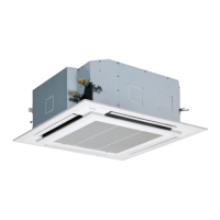
<4-way cassette type>
MMU-UP0091HP-E(TR)
MMU-UP0121HP-E(TR)
MMU-UP0151HP-E(TR)
MMU-UP0181HP-E(TR)
MMU-UP0241HP-E(TR)
MMU-UP0271HP-E(TR)
MMU-UP0301HP-E(TR)
MMU-UP0361HP-E(TR)
MMU-UP0481HP-E(TR)
MMU-UP0561HP-E(TR)
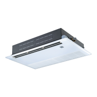
<Ceiling type>
MMC-UP0151HP-E(TR)
MMC-UP0181HP-E(TR)
MMC-UP0241HP-E(TR)
MMC-UP0271HP-E(TR)
MMC-UP0361HP-E(TR)
MMC-UP0481HP-E(TR)
MMC-UP0561HP-E(TR)
<Concealed Duct Standard type>
MMD-UP0051BHP-E
MMD-UP0071BHP-E(TR)
MMD-UP0091BHP-E(TR)
MMD-UP0121BHP-E(TR)
MMD-UP0151BHP-E(TR)
MMD-UP0181BHP-E(TR)
MMD-UP0241BHP-E(TR)
MMD-UP0271BHP-E(TR)
MMD-UP0301BHP-E(TR)
MMD-UP0361BHP-E(TR)
MMD-UP0481BHP-E(TR)
MMD-UP0561BHP-E(TR)
<Concealed Duct High Static Pressure type>
MMD-UP0181HP-E(TR)
MMD-UP0241HP-E(TR)
MMD-UP0271HP-E(TR)
MMD-UP0361HP-E(TR)
MMD-UP0481HP-E(TR)
MMD-UP0561HP-E(TR)
MMD-UP0721HP-E(TR)
MMD-UP0961HP-E(TR)
<Concealed Duct High Static Pressure
fresh air intake type>
MMD-UP0481HFP-E(TR)
MMD-UP0721HFP-E(TR)
MMD-UP0961HFP-E(TR)
MMD-UP1121HFP-E(TR)
MMD-UP1281HFP-E(TR)
<Console type>
MML-UP0071NHP-E(TR)
MML-UP0091NHP-E(TR)
MML-UP0121NHP-E(TR)
MML-UP0151NHP-E(TR)
MML-UP0181NHP-E(TR)
<High wall type>
MMK-UP0031HP-E(TR)
MMK-UP0051HP-E(TR)
MMK-UP0071HP-E(TR)
MMK-UP0091HP-E(TR)
MMK-UP0121HP-E(TR)
MMK-UP0151HP-E(TR)
MMK-UP0181HP-E(TR)
MMK-UP0241HP-E(TR)
MMK-UP0031HPL-E(TR)
MMK-UP0051HPL-E(TR)
MMK-UP0071HPL-E(TR)
MMK-UP0091HPL-E(TR)
MMK-UP0121HPL-E(TR)
MMK-UP0151HPL-E(TR)
MMK-UP0181HPL-E(TR)
MMK-UP0241HPL-E(TR)
FILE NO. SVM-20095
January, 2021

Table of Contents

Other manuals for Toshiba MMU-UP0181HP-E

Questions and Answers:

Toshiba MMU-UP0181HP-E Specifications

General IconGeneral
CategoryAir Conditioner
Power Supply220-240V, 50Hz
Energy Efficiency Ratio (EER)3.21
Coefficient of Performance (COP)3.61
RefrigerantR410A
Noise Level (Outdoor Unit)50 dB

Summary

1. SPECIFICATIONS

1-1. 4-way cassette type

Specifications for the 4-way cassette indoor unit.

1-2. Ceiling type

Specifications for the ceiling type indoor unit.

1-3. Concealed Duct Standard type

Specifications for the concealed duct standard indoor unit.

1-4. Concealed Duct High Static Pressure type

Specifications for the concealed duct high static pressure indoor unit.

1-5. Concealed Duct High Static Pressure fresh air intake type

Specifications for the concealed duct high static pressure fresh air intake indoor unit.

1-6. Console type

Specifications for the console type indoor unit.

1-7. High wall type

Specifications for the high wall indoor unit.

2. CONSTRUCTION VIEWS (EXTERNAL VIEWS)

2-1. 4-way cassette type

External views and dimensions for the 4-way cassette indoor unit.

2-2. Ceiling type

External views and dimensions for the ceiling type indoor unit.

2-3. Concealed Duct Standard type

External views and dimensions for the concealed duct standard indoor unit.

2-4. Concealed Duct High Static Pressure type

External views and dimensions for the concealed duct high static pressure indoor unit.

2-5. Concealed Duct High Static Pressure fresh air intake type

External views and dimensions for the concealed duct high static pressure fresh air intake indoor unit.

2-6. Console type

External views and dimensions for the console type indoor unit.

2-7. High wall type

External views and dimensions for the high wall indoor unit.

3. WIRING DIAGRAMS

3-1. 4-way cassette type

Wiring diagrams for the 4-way cassette indoor unit.

3-2. Ceiling type

Wiring diagrams for the ceiling type indoor unit.

3-3. Concealed Duct Standard type

Wiring diagrams for the concealed duct standard indoor unit.

3-4. Concealed Duct High Static Pressure type

Wiring diagrams for the concealed duct high static pressure indoor unit.

3-5. Concealed Duct High Static Pressure fresh air intake type

Wiring diagrams for the concealed duct high static pressure fresh air intake indoor unit.

3-6. Console type

Wiring diagrams for the console type indoor unit.

3-7. High wall type

Wiring diagrams for the high wall indoor unit.

8. APPLIED CONTROL AND FUNCTIONS (INCLUDING CIRCUIT CONFIGURATION)

8-1. Indoor controller block diagram (MCC-1643)

Block diagram of the indoor controller MCC-1643 for applied control functions.

8-2. Indoor controller block diagram (MCC-1720)

Block diagram of the indoor controller MCC-1720 for applied control functions.

8-3. Indoor controller block diagram (MCC-1696)

Block diagram of the indoor controller MCC-1696 for applied control functions.

8-4. Indoor Print Circuit Board

Details on the indoor unit print circuit board layout and components.

9. TROUBLESHOOTING

9-1. Overview

General overview of troubleshooting procedures and applicable models.

9-2. Troubleshooting method

Detailed methods for diagnosing and resolving unit issues based on check codes.

9-3. Troubleshooting based on information displayed on remote controller

Troubleshooting using information displayed on the remote controller.

9-5. Diagnostic Procedure for Each Check Code (Indoor Unit)

Diagnostic procedures for specific check codes detected by the indoor unit.

9-6. Sensor characteristics

Resistance characteristics of indoor unit temperature sensors for diagnosis.

9-7. Maintenance list

Recommended maintenance schedule for indoor and outdoor units.

10. P.C. BOARD EXCHANGE PROCEDURES

Indoor unit

Procedures specific to indoor unit P.C. board replacement.

10-1. Replacement of indoor P.C. boards

Procedures for replacing the indoor unit P.C. board, including data backup.

11. DETACHMENTS

11-1. 4-way cassette type

Procedures for detaching parts of the 4-way cassette indoor unit.

11-2. Ceiling type

Procedures for detaching parts of the ceiling type indoor unit.

11-3. Concealed Duct Standard type

Procedures for detaching parts of the concealed duct standard indoor unit.

11-4. Concealed Duct High Static Pressure type

Procedures for detaching parts of the concealed duct high static pressure indoor unit.

11-5. Concealed Duct High Static Pressure fresh air intake type

Procedures for detaching parts of the concealed duct high static pressure fresh air intake indoor unit.

11-6. Console type

Procedures for detaching parts of the console type indoor unit.

11-7. High wall type

Procedures for detaching parts of the high wall indoor unit.

12. EXPLODED VIEWS AND PARTS LIST

12-1. 4-way cassette type

Exploded view and parts list for the 4-way cassette indoor unit.

12-2. Ceiling type

Exploded view and parts list for the ceiling type indoor unit.

12-3. Concealed Duct Standard type

Exploded view and parts list for the concealed duct standard indoor unit.

12-4. Concealed Duct High Static Pressure type

Exploded view and parts list for the concealed duct high static pressure indoor unit.

12-5. Concealed Duct High Static Pressure fresh air intake type

Exploded view and parts list for the concealed duct high static pressure fresh air intake indoor unit.

12-6. Console type

Exploded view and parts list for the console type indoor unit.

12-7. High wall type

Exploded view and parts list for the high wall indoor unit.

PRECAUTIONS FOR SAFETY

Declaration of Conformity

4. PARTS RATING

4-way cassette type

Parts rating for the 4-way cassette indoor unit models.

Ceiling type

Parts rating for the ceiling type indoor unit models.

Concealed Duct Standard type

Parts rating for the concealed duct standard indoor unit models.

Concealed Duct High Static Pressure type

Parts rating for the concealed duct high static pressure indoor unit models.

Concealed Duct High Static Pressure Fresh air intake type

Parts rating for the concealed duct high static pressure fresh air intake indoor unit models.

Console type

Parts rating for the console type indoor unit models.

High wall type

Parts rating for the high wall indoor unit models.

5. REFRIGERANT CYCLE DIAGRAM

Indoor unit

Diagram illustrating the refrigerant cycle within the indoor unit.

6. CONTROL OUTLINE

Control Specifications

Overview of the air conditioner's control specifications and functions.

7. COMMUNICATION TYPE, MODEL NAMES AND THE MAXIMUM NUMBER OF CONNECTABLE UNITS

8. APPLIED CONTROL AND FUNCTIONS (INCLUDING CIRCUIT CONFIGURATION)

8-1. Indoor controller block diagram (MCC-1643)

Block diagram of the indoor controller MCC-1643 for applied control functions.

8-1-1. In case of connection of wired remote controller

Wiring configuration for indoor controller MCC-1643 with wired remote controller.

8-1-2. In case of connection of wireless remote controller

Wiring configuration for indoor controller MCC-1643 with wireless remote controller.

8-1-3. Connection of both wired remote controller and wireless remote controller

Wiring configuration for indoor controller MCC-1643 with both wired and wireless controllers.

8-2. Indoor controller block diagram (MCC-1720)

Block diagram of the indoor controller MCC-1720 for applied control functions.

8-2-1. In case of connection of wired remote controller

Wiring configuration for indoor controller MCC-1720 with wired remote controller.

8-2-2. In case of connection of wireless remote controller

Wiring configuration for indoor controller MCC-1720 with wireless remote controller.

8-2-3. In case of connection of wired remote controller and wireless remote controller

Wiring configuration for indoor controller MCC-1720 with both wired and wireless controllers.

8-3. Indoor controller block diagram (MCC-1696)

Block diagram of the indoor controller MCC-1696 for applied control functions.

8-3-1. Connection of wired remote controller

Wiring configuration for indoor controller MCC-1696 with wired remote controller.

8-3-2. Connection of Wireless Remote Controller

Wiring configuration for indoor controller MCC-1696 with wireless remote controller.

8-4. Indoor Print Circuit Board

Details on the indoor unit print circuit board layout and components.

Optional connector specifications of indoor P.C. board (MCC-1643)

Specifications for optional connectors on the MCC-1643 indoor P.C. board.

8-4-2. MCC-1720

Details on the MCC-1720 indoor P.C. board layout and components.

Optional connector specifications of indoor P.C. board (MCC-1720)

Specifications for optional connectors on the MCC-1720 indoor P.C. board.

8-4-3. MCC-1696

Details on the MCC-1696 indoor P.C. board layout and components.

Optional connector specifications of indoor P.C. board (MCC-1696)

Specifications for optional connectors on the MCC-1696 indoor P.C. board.

8-5. Test run of indoor unit

Cooling/Heating test run check

Procedure for performing cooling and heating test runs on the indoor unit.

Check function for operation of indoor unit (Functions at indoor unit side)

[How to operate]

Steps to operate the indoor unit functions directly from the unit.

[How to clear]

Procedure to clear the current operation status and return to normal.

8-6. Method to set indoor unit function DN code

8-7. Applied control of indoor unit

Control system using Remote location ON/OFF control box (TCB-IFCB-4E2)

Details on applying control using the remote ON/OFF control box.

Ventilating fan control from remote controller

1. Operation

Procedure for operating the ventilating fan using the wired remote controller.

2. Wiring

Wiring instructions for connecting the ventilating fan control.

Auto-off feature control

(1) Wiring

Wiring setup for the auto-off feature control.

(2) Code (DN) setup

Setting the Code (DN) for the auto-off feature control.

Notice code signal

(1) Wiring

Wiring instructions for the notice code signal function.

(2) Code (DN) setup and Notice code

Setting the Code (DN) and notice code for the communication signal.

Manual address setting using the remote controller

<Line (system) address>

Procedure to set the line (system) address for indoor units.

<Indoor unit address>

<Group address>

<Line (system) address>

<Indoor unit address>

<Group address>

Confirming the indoor unit addresses and the position of an indoor unit using the remote controller

Confirming the numbers and positions of indoor units

Procedure to confirm indoor unit numbers and positions via remote controller.

To find an indoor unit’s position from its address

When checking unit numbers controlled as a group

Procedure to check indoor unit numbers within a group.

To check all the indoor unit addresses using an arbitrary wired remote controller.

To select another system address

Procedure to select and check different system addresses.

Changing the indoor unit address using a remote controller

To change an indoor unit address using a wired remote controller.

Method for changing an indoor unit's address via wired remote controller.

To change all the indoor unit addresses using an arbitrary wired remote controller.

Check code clearing function

How to clear the check code using the wired remote controller

Procedure for clearing check codes using the wired remote controller.

Clearing a check code of the outdoor unit

Steps to clear check codes for the outdoor unit via remote controller.

Clearing a check code of the indoor unit

Steps to clear check codes specific to the indoor unit.

Monitoring function of wired remote controller

Indoor service monitor list

Indoor unit data *

List of service data parameters for indoor units and their display formats.

9. TROUBLESHOOTING

9-1. Overview

General overview of troubleshooting procedures and applicable models.

9-2. Troubleshooting method

Detailed methods for diagnosing and resolving unit issues based on check codes.

9-3. Troubleshooting based on information displayed on remote controller

Troubleshooting using information displayed on the remote controller.

9-5. Diagnostic Procedure for Each Check Code (Indoor Unit)

Diagnostic procedures for specific check codes detected by the indoor unit.

9-6. Sensor characteristics

Resistance characteristics of indoor unit temperature sensors for diagnosis.

9-7. Maintenance list

Recommended maintenance schedule for indoor and outdoor units.

10. P.C. BOARD EXCHANGE PROCEDURES

Indoor unit

Procedures for servicing and replacing indoor unit P.C. boards.

10-1. Replacement of indoor P.C. boards

Procedures for replacing the indoor unit P.C. board, including data backup.

11. DETACHMENTS

11-1. 4-way cassette type

Procedures for detaching parts of the 4-way cassette indoor unit.

11-2. Ceiling type

Procedures for detaching parts of the ceiling type indoor unit.

11-3. Concealed Duct Standard type

Procedures for detaching parts of the concealed duct standard indoor unit.

11-4. Concealed Duct High Static Pressure type

Procedures for detaching parts of the concealed duct high static pressure indoor unit.

11-5. Concealed Duct High Static Pressure fresh air intake type

Procedures for detaching parts of the concealed duct high static pressure fresh air intake indoor unit.

11-6. Console type

Procedures for detaching parts of the console type indoor unit.

11-7. High wall type

Procedures for detaching parts of the high wall indoor unit.

12. EXPLODED VIEWS AND PARTS LIST

12-1. 4-way cassette type

Exploded view and parts list for the 4-way cassette indoor unit.

12-2. Ceiling type

Exploded view and parts list for the ceiling type indoor unit.

12-3. Concealed Duct Standard type

Exploded view and parts list for the concealed duct standard indoor unit.

12-4. Concealed Duct High Static Pressure type

Exploded view and parts list for the concealed duct high static pressure indoor unit.

12-5. Concealed Duct High Static Pressure fresh air intake type

Exploded view and parts list for the concealed duct high static pressure fresh air intake indoor unit.

12-6. Console type

Exploded view and parts list for the console type indoor unit.

12-7. High wall type

Exploded view and parts list for the high wall indoor unit.

Related product manuals