– 35 –
SMMS wave tool
“SMMS wave tool” is an application software (“Application”) for the Android OS smartphone and for those who
install and do maintenance to the compatible air conditioning equipment. The Application enables checks of some
of the system and data and test operations of compatible air conditioning equipment. Please check the information
about compatible air conditioning equipment and smartphone from the below URL. Be sure to read
the Operating Manual before the use of this Application, “SMMS wave tool”. You can download the
Application and the Operating Manual from the below URL or QR code. QR code is a trademark
or registered trademark of DENSO WAVE Inc.Android is a trademark or registered trademark of
Google Inc.
URL : http://www.toshiba-carrier.co.jp/global/appli/smms_wave_tool/
NOTICE
This Application enables the auto-address setup and the test operation of the outdoor unit by smartphone in
48 hours from the power input to the outdoor unit.
You should decide whether to make use of this auto-address setup and test operation function at its own
responsibility and also be sure to confirm notices in the Operating Manual before performing the test operation.
If you want to disable the function of the auto-address setup and the test operation, perform the following
operations.
Refer to the service manual for setting change of the auto-address setup and the test operation function to be
effective.
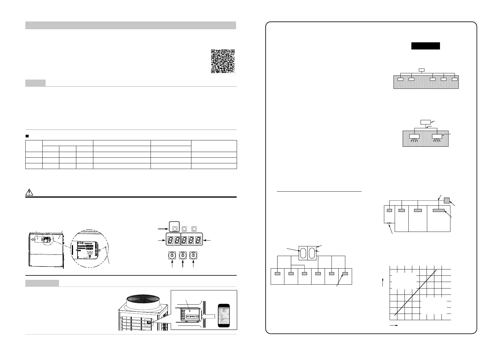
Switch setting of some functions prohibition
Step
Rotary switch Push switch 7-segment display
Condition
SW01 SW02 SW03 SW04 [ A ] [ B ]
(1) 2 1 14 - [ nf ] [ c.00 ] Setting preparation
(2) 2 1 14 Press for more than 5 secs [ nf ] [ c.01 ] Setting completion
(3) 1 1 1 - [ U.1. ] [ - - - ] Return the switch
* Do it again if the 7-segment display is different from the above.
* The functions other than the auto-address setup and test operation of this Application can work normally even if
the auto-address set up and test operation function are disabled.
CAUTION
High voltage parts exist in the electrical control box.
If you set Switch setting, set it from the access door cover of the electrical control box cover to avoid electric
shock.
After finishing operations, slide the access door cover to the position before and fix it with the screw.
SW04
SW01 SW02
SW03
D600 D601 D602 D603 D604
SW05 SW15
Access
door cover
Cover of the electrical
control box
Fixing screw for the
access door cover
Push switch
7-segment
display [A]
7-segment
display [B]
Rotary switches
HOW TO USE
This Application uses the NFC (Near Field
Communication) function of smartphone.
For the use, hold your smartphone to the
“TOUCH” mark of the outdoor unit.
Refer to the Operating Manual of the “SMMS
wave tool” for the details.
NFC receiver for
SMMS wave tool
Smartphone
Outdoor unit
QR code
WARNINGS ON REFRIGERANT LEAKAGE
Check of Concentration Limit
The room in which the air conditioner is to be installed
requires a design that in the event of refrigerant gas
leaking out, its concentration will not exceed a set
limit.
The refrigerant R410A which is used in the air conditioner is
safe, without the toxicity or combustibility of ammonia, and
is not restricted by laws to be imposed which protect the
ozone layer. However, since it contains more than air,
it poses the risk of suffocation if its concentration should rise
excessively.
Suffocation from leakage of R410A is almost non-existent.
With the recent increase in the number of high concentration
buildings, however, the installation of multi air conditioner
systems is on the increase because of the need for effective
use of floor space, individual control, energy conservation
by curtailing heat and carrying power etc.
Most importantly, the multi air conditioner system is able
to replenish a large amount of refrigerant compared with
conventional individual air conditioners. If a single unit of the
multi conditioner system is to be installed in a small room,
select a suitable model and installation procedure so that
if the refrigerant accidentally leaks out, its concentration
does not reach the limit (and in the event of an emergency,
measures can be made before injury can occur).
In a room where the concentration may exceed the
limit, create an opening with adjacent rooms, or install
mechanical ventilation combined with a gas leak detection
device.
The concentration is as given below.
Total amount of refrigerant (kg)
Min. volume of the indoor unit installed room (m
3
)
Concentration limit (kg/m
3
)
The concentration limit of R410A which is used in multi
air conditioners is 0.3 kg/m
3
.
NOTE 1 :
If there are 2 or more refrigerating systems in a single
refrigerating device, the amounts of refrigerant should be
as charged in each independent device.
e.g., charged
amount (10 kg)
e.g.,
charged amount (15 kg)
Outdoor unit
Indoor unit
Room A Room B Room C Room D Room E Room F
For the amount of charge in this example:
The possible amount of leaked refrigerant gas in rooms
A, B and C is 10 kg.
The possible amount of leaked refrigerant gas in rooms
D, E and F is 15 kg.
Important
NOTE 2 :
The standards for minimum room volume are as follows.
(1) No partition (shaded portion)
(2) When there is an effective opening with the adjacent
room for ventilation of leaking refrigerant gas
(opening without a door, or an opening 0.15% or
larger than the respective floor spaces at the top or
bottom of the door).
Outdoor unit
Refrigerant piping
Indoor unit
(3) If an indoor unit is installed in each partitioned
room and the refrigerant piping is interconnected,
the smallest room of course becomes the object.
But when a mechanical ventilation is installed
interlocked with a gas leakage detector in the
smallest room where the density limit is exceeded,
the volume of the next smallest room becomes the
object.
Refrigerant piping
Outdoor unit
Indoor unit
Very
small
room
Small
room
Medium
room
Large room
Mechanical ventilation device - Gas leak detector
NOTE 3 :
The minimum indoor floor area compared with the
amount of refrigerant is roughly as follows:
(When the ceiling is 2.7 m high).
0
5
10
10 20 30
15
20
25
30
35
40
m
2
Total amount of refrigerant kg
Range below the
density limit of
0.3 kg/m
3
(countermeasures
not needed)
Range above the
density limit of
0.3 kg/m
3
(countermeasures
needed)
Min. indoor floor area
69-EN 70-EN
 Loading...


