EasyManua.ls Logo

Toshiba MMY-MAP0804HT8JP User Manual

Toshiba MMY-MAP0804HT8JP
323 pages
To Next Page IconTo Next Page
Page #1 background imageLoading...
Page #1 background image
SERVICE MANUAL
AIR-CONDITIONER (MULTI TYPE)
<SUPER MODULAR MULTI SYSTEM - i>
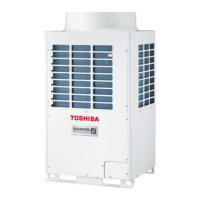
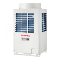
Outdoor Unit
Model name:
FILE NO. SVM-13024-2
MMY-MAP0804HT8(J)P
MMY-MAP1004HT8(J)P
MMY-MAP1204HT8(J)P
MMY-MAP1404HT8(J)P
MMY-MAP1604HT8(J)P
MMY-MAP0804HT8(J)P-E
MMY-MAP1004HT8(J)P-E
MMY-MAP1204HT8(J)P-E
MMY-MAP1404HT8(J)P-E
MMY-MAP1604HT8(J)P-E
MMY-MAP0804HT8(J)P-TR
MMY-MAP1004HT8(J)P-TR
MMY-MAP1204HT8(J)P-TR
MMY-MAP1404HT8(J)P-TR
MMY-MAP1604HT8(J)P-TR
<Heat Pump Model>
<4-way Cassette Type>
(MMU-AP***4HP-E) (Made in Thailand model) SVM-13-011
<2-way Cassette Type>
(MMU-AP
***
2WH) A10-007
<Concealed Duct Standard Type>
(MMD-AP
***
6BH-E) A12-005
<Slim Duct Type>
(MMD-AP0244SPH-E, AP0274SPH-E) A12-005
Fresh Air Intake Indoor Unit Type
(MMD-AP
****
HFE) A06-016
<Air to Air Heat Exchanger with DX Coil Unit Type>
(MMD-VN
*****
HEXE
*
) A10-022-2
High-wall Type
(MMK-AP
***
3H) (Made in Thailand model) SVM-09-059
Console Type
(MML-AP
****
NH-E) (Made in Thailand model) SVM-11-036
Other indoor units
(MM
*
-AP
*****
H
*
) A10-033
MMY-MAP0804HT7(J)P
MMY-MAP1004HT7(J)P
MMY-MAP1204HT7(J)P
MMY-MAP1404HT7(J)P
MMY-MAP1604HT7(J)P
MMY-MAP0804T8(J)P
MMY-MAP1004T8(J)P
MMY-MAP1204T8(J)P
MMY-MAP1404T8(J)P
MMY-MAP1604T8(J)P
MMY-MAP0804T8(J)P-T
MMY-MAP1004T8(J)P-T
MMY-MAP1204T8(J)P-T
MMY-MAP1404T8(J)P-T
MMY-MAP1604T8(J)P-T
MMY-MAP0804T8(J)P-SG
MMY-MAP1004T8(J)P-SG
MMY-MAP1204T8(J)P-SG
MMY-MAP1404T8(J)P-SG
MMY-MAP1604T8(J)P-SG
<Cooling Only Model>
MMY-MAP0804T8(J)P-ID
MMY-MAP1004T8(J)P-ID
MMY-MAP1204T8(J)P-ID
MMY-MAP1404T8(J)P-ID
MMY-MAP1604T8(J)P-ID
This service manual provides relevant explanations about new outdoor unit (SMMS-i).
Please refer to the following service manuals for each indoor units.

Table of Contents

Questions and Answers:

Toshiba MMY-MAP0804HT8JP Specifications

General IconGeneral
BrandToshiba
ModelMMY-MAP0804HT8JP
CategoryAir Conditioner
LanguageEnglish

Summary

Wiring Diagrams

Combined Refrigerant Piping System Schematic Diagrams

4-1. Normal Operation (COOL Mode / DEFROST Mode) - High Outside Air Temperature (Roughly 20°C or Above)

Schematic illustrating refrigerant flow during normal cooling and defrost under high ambient temperatures.

4-2. Normal Operation (COOL Mode) - Low Outside Air Temperature (Roughly Below 20°C)

Schematic illustrating refrigerant flow during normal cooling under low ambient temperatures.

4-3. Normal Operation (HEAT Mode)

Schematic illustrating refrigerant flow during normal heating operation.

4-4. Emergency Operation (Cooling Operation under Header Outdoor Unit Backup Scenario)

Refrigerant diagram for emergency cooling operation with backup header unit.

4-5. Emergency Operation (Heating Operation under Header Outdoor Unit Backup Scenario)

Refrigerant diagram for emergency heating operation with backup header unit.

4-6. Refrigerant Recovery from Failed Outdoor Unit (Pump-Down Operation under Follower Outdoor Unit Backup Scenario)

Schematic for refrigerant recovery during pump-down, with follower unit backup.

Control Outline

Pulse motor valve (PMV) control

Details on PMV1, 2, and 4 control based on operating conditions, pressure, and temperature sensors.

Oil level detection control

Judgment of optimum oil level in compressor cases based on TK1 to TK5 sensor readings.

Oil equation control

Function to prevent compressors from running out of oil by evening out oil supply between outdoor units.

Refrigerant/oil recovery control

Procedures for indoor units during outdoor unit refrigerant or oil recovery operations.

Defrosting control (reverse defrosting method)

Conditions and details for initiating, performing, and terminating defrosting control.

Release valve control

Control functions for SV2, SV4, and SV5 valves related to gas balance, pressure release, and protection.

High pressure release compressor shutdown control

Function to automatically shut down a compressor based on high Pd pressure.

A3-IPDU control

Controls related to inverter compressors, including current release, heat sink temperature, and overcurrent protection.

Applied Control and Functions (including Circuit Configuration)

6-1. Indoor Controller Block Diagram

Block diagrams showing circuit configuration for wired, wireless, and mixed remote controller setups.

6-4. Test Operation of Indoor Unit

Procedure to check indoor unit operation and fan system independently of the remote controller or outdoor unit.

TEST OPERATION

7-2. Check Items before Test Operation (before powering-on)

Essential checks for electric wiring and connections prior to powering on the system.

7-4. Address Setup

Procedures for setting and verifying addresses for indoor, outdoor, and central control units.

7-5. Troubleshooting in Test Operation

Troubleshooting guide for issues encountered during test operations and check code displays.

7-6. Test Operation Check

Procedures for checking fan operation and performing single cooling/heating test operations.

7-7. Service Support Function

Various service functions accessible via switches on the outdoor unit interface P.C. board.

TROUBLESHOOTING

8-2. Troubleshooting Method

Method for identifying fault sites and parts using check codes displayed on controllers and interface boards.

8-3. Troubleshooting Based on Information Displayed on Remote Controller

Troubleshooting guide based on check codes and error history displayed on the remote controller.

8-4. Check Codes Displayed on Remote Controller and SMMS-i Outdoor Unit (7-Segment Display on I/F Board) and Locations to Be Checked

Table correlating check codes from remote controllers and outdoor units with their causes and locations.

8-5. Diagnosis procedure for each check code

Flowcharts providing step-by-step diagnosis procedures for various check codes.

8-8. Leakage/Clogging of Refrigerating Cycle Circuit

List of check codes generated due to leakage or clogging in the refrigerant or oil circuit.

BACKUP OPERATION (EMERGENCY OPERATION)

9-2. Compressor Backup Operation Setting

Procedure for setting compressor backup operation using DIP switches on the outdoor unit interface.

9-3. Outdoor Unit Backup Operation Setting

Setting procedures for outdoor unit backup operation in case of unit failure.

9-4. Cooling-Season Outdoor Unit Backup Operation Setting

Procedure for setting backup operation specifically for cooling season when heating is not required.

OUTDOOR UNIT REFRIGERANT RECOVERY METHOD

10-1. Refrigerant Recovery from Failed Outdoor Unit (Pump-Down)

Supports refrigerant pump-down to recover refrigerant from a failed outdoor unit using a normal outdoor unit.

REPLACING COMPRESSORS

11-1. Compressor Replacement Procedure (Outline)

General outline for replacing a compressor, including safety precautions and oil management.

11-2. Replacement of Compressors

Detailed procedure for replacing compressors, including oil adjustment and handling of normal units.

SAFETY CAUTION

Warning Indications on the Air Conditioner Unit

Installation

SELECTION OF PIPE SIZE

Adding refrigerant

New Refrigerant (R410A)

1. Safety Caution Concerned to New Refrigerant

Safety warnings and precautions related to the use of R410A refrigerant.

Tools

Outdoor (Inverter) Print Circuit Board

OUTDOOR UNIT PARTS REPLACEMENT METHODS

P.C. BOARD EXCHANGE PROCEDURES

Replacement of Outdoor P.C. Boards

REFRIGERATION CIRCUIT DIAGRAM

Related product manuals