EasyManua.ls Logo

Toshiba MMY-MAP0804T8P-SG User Manual

Toshiba MMY-MAP0804T8P-SG
370 pages
To Next Page IconTo Next Page
Page #1 background imageLoading...
Page #1 background image
AIR CONDITIONER (MULTI TYPE)
SERVICE MANUAL
FILE No. A10-005
This service manual provides relevant explanations about new outdoor unit (SMMS-i). Please refer to
the following service manuals for each indoor units.
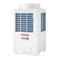
Outdoor Unit
<SUPER MODULAR MULTI SYSTEM-i>
Model name:
<Heat Pump Model>
<Cooling Only Model>
4-way Air Discharge Cassette Type
(MMU-AP 2H)
A08-004
Compact 4-way Cassette (600 × 600) Type
(MMU-AP 1MH)
A06-002
1-way Air Discharge Cassette Type SH (2 series)
(MMU-AP 2SH)
A05-007
2-way Air Discharge Cassette Type (2 series)
(MMU-AP 2WH)
A10-007
Slim Duct Type
(MMD-AP 1SPH)
A05-007
Fresh Air Intake Indoor Unit Type
(MMD-AP 1HFE)
A06-016
High-wall Type (2 series)
(MMK-AP 2H)
A05-005
High-wall Type (3 series)
(MMK-AP 3H)
SVM-09059
Other indoor units SMMS (1 series) A03-009, A03-010
MMY-MAP0804HT8(Z)(ZG)-E
MMY-MAP1004HT8(Z)(ZG)-E
MMY-MAP1204HT8(Z)(ZG)-E
MMY-MAP1404HT8(Z)(ZG)-E
MMY-MAP1604HT8(Z)(ZG)-E
MMY-MAP0804HT8(Z)(ZG)-TR
MMY-MAP1004HT8(Z)(ZG)-TR
MMY-MAP1204HT8(Z)(ZG)-TR
MMY-MAP1404HT8(Z)(ZG)-TR
MMY-MAP1604HT8(Z)(ZG)-TR
MMY-MAP0804HT8(Z)(ZG)
MMY-MAP1004HT8(Z)(ZG)
MMY-MAP1204HT8(Z)(ZG)
MMY-MAP1404HT8(Z)(ZG)
MMY-MAP1604HT8(Z)(ZG)
MMY-MAP0804HT7(Z)(ZG)
MMY-MAP1004HT7(Z)(ZG)
MMY-MAP1204HT7(Z)(ZG)
MMY-MAP1404HT7(Z)(ZG)
MMY-MAP1604HT7(Z)(ZG)
MMY-MAP0804T8(Z)(ZG)-E
MMY-MAP1004T8(Z)(ZG)-E
MMY-MAP1204T8(Z)(ZG)-E
MMY-MAP1404T8(Z)(ZG)-E
MMY-MAP1604T8(Z)(ZG)-E
MMY-MAP0804T8(Z)(ZG)
MMY-MAP1004T8(Z)(ZG)
MMY-MAP1204T8(Z)(ZG)
MMY-MAP1404T8(Z)(ZG)
MMY-MAP1604T8(Z)(ZG)
MMY-MAP0804T8-SG
MMY-MAP1004T8-SG
MMY-MAP1204T8-SG
MMY-MAP1404T8-SG
MMY-MAP1604T8-SG

Table of Contents

Questions and Answers:

Toshiba MMY-MAP0804T8P-SG Specifications

General IconGeneral
BrandToshiba
ModelMMY-MAP0804T8P-SG
CategoryAir Conditioner
LanguageEnglish

Summary

1 Wiring Diagrams

1-1. Outdoor Unit

Wiring diagrams for outdoor units MMY-MAP0804, MAP1004, and MAP1204.

1-2. Indoor Unit

Wiring diagrams for various indoor unit types, including cassette, duct, and wall units.

2 Parts Rating

2-1. Outdoor Unit (50Hz model: MMY-MAP***4HT8-E, MAP4HT8-TR, MAP4HT8, MAP4T8-SG)

Parts rating for 50Hz outdoor units, listing components and specifications.

2-2. Outdoor Unit (60Hz model: MMY-MAP***4HT7)

Parts rating for 60Hz outdoor units, listing components and specifications.

2-3. Outdoor Inverter (50Hz model: MMY-MAP***4HT8-E, MAP4HT8-TR, MAP4HT8, MAP4T8-SG)

Parts rating for 50Hz outdoor inverter models, listing components.

2-4. Outdoor Inverter (60Hz model: MMY-MAP***4HT7)

Parts rating for 60Hz outdoor inverter models, listing components.

2-5. Indoor Unit

Parts rating for various indoor unit types, categorized by model.

2-6. Parts Layout in Outdoor Unit

Exploded diagram showing parts layout for outdoor units (8, 10, 12HP).

2-7. Parts Layout in Inverter Assembly

Component layout for inverter assembly in outdoor units (8, 10, 12HP).

2-8. Outdoor (Inverter) Print Circuit Board

Details of interface, compressor, and fan IPDU print circuit boards.

3 Refrigerant Piping Systematic Drawing

4 Combined Refrigerant Piping System Schematic Diagrams

4-1. Normal Operation (COOL Mode / DEFROST Mode) - High Outside Air Temperature (Roughly 20 °C or Above)

Refrigerant flow during normal cooling/defrost at high outside air temperatures.

4-2. Normal Operation (COOL Mode) - Low Outside Air Temperature (Roughly Below 20 °C)

Refrigerant flow during normal cooling at low outside air temperatures.

4-3. Normal Operation (HEAT Mode)

Refrigerant flow during normal heating operation.

4-4. Emergency Operation (Cooling Operation under Header Outdoor Unit Backup Scenario)

Refrigerant flow during emergency cooling with header backup.

4-5. Emergency Operation (Heating Operation under Header Outdoor Unit Backup Scenario)

Refrigerant flow during emergency heating with header backup.

4-6. Refrigerant Recovery from Failed Outdoor Unit (Pump-Down Operation under Follower Outdoor Unit Backup Scenario)

Refrigerant recovery procedure when an outdoor unit fails and a follower unit provides backup.

5 Control Outline

5-1. Indoor Unit Control Specifications

Outlines control specifications for indoor units, including operation selection and temperature control.

5-2. Fan Speed Control

Details fan speed control modes and operation based on temperature and operating conditions.

5-3. Freeze Prevention Control (Low Temp. Release)

Controls operation during low temperature conditions to prevent freezing.

5-4. Cold Air Discharge Prevention Control

Prevents cold air discharge during heating operation.

5-5. Oil Level Detection Control

Monitors and controls oil levels in compressors for proper lubrication.

5-6. Oil Equation Control

Manages oil distribution between compressors to prevent oil shortage.

5-7. Refrigerant/Oil Recovery Control

Procedures for recovering cooling oil and heating refrigerant/oil.

5-8. Defrosting Control (Reverse Defrosting Method)

Details the defrosting process, including commencement and termination conditions.

6 Applied Control and Functions (including Circuit Configuration)

6-1. Indoor Controller Block Diagrams

Block diagrams showing indoor controller configurations with different remote controller setups.

6-2. Indoor Printed Circuit Board Details

Detailed diagram of the indoor unit's main printed circuit board (MCC-1570).

6-3. Optional Connector Specifications (Indoor P.C. Board)

Specifications for optional connectors on the indoor P.C. board, detailing functions.

6-4. Indoor Unit Test Operation

Procedure for testing indoor unit operation independently.

6-5. Setting Indoor Unit Function DN Codes

Procedure to set various indoor unit functions using DN codes via remote controller.

6-6. Applied Control of Indoor Unit

Details on applied control functions for indoor units.

6-7. Applied Control for Outdoor Unit

Details applied controls for outdoor units like fan speed, peak-cut, and mode selection.

6-8. Applied Control of Outdoor Unit

Details applied controls for outdoor units like power peak-cut, snowfall, and error output.

7 TEST OPERATION

7-1. Procedure and Summary of Test Operation

Step-by-step guide for executing a test operation.

7-2. Check Items before Test Operation (before powering-on)

Essential checks of electric wiring and system connections before test operation.

7-3. Check at Main Power-on

Checks performed after applying main power for test operation.

7-4. Address Setup Procedures

Procedures for setting and verifying system addresses for all connected units.

8 TROUBLESHOOTING

8-1. Overview

General approach to troubleshooting and required tools.

8-2. Troubleshooting Method (Check Codes)

Lists check codes detected by various devices and their fault sites for analysis.

8-3. Troubleshooting Based on Information Displayed on Remote Controller

Diagnosing faults based on information displayed on remote controllers (main and central).

8-5. Diagnosis procedure for each check code

Flowcharts guiding diagnosis for specific system check codes.

9 BACKUP OPERATION (EMERGENCY OPERATION)

9-1. Note for Backup Operation

Important notes and conditions for backup operation based on fault types.

9-2. Compressor Backup Operation Setting

Procedure for setting up compressor backup operation when a compressor fails.

9-3. Outdoor Unit Backup Operation Setting

Procedures for setting up outdoor unit backup operation when a unit fails.

9-4. Cooling-Season Outdoor Unit Backup Operation Setting

Procedure for backup operation specifically for the cooling season.

10 OUTDOOR UNIT REFRIGERANT RECOVERY METHOD

10-1. Refrigerant Recovery from Failed Outdoor Unit (Pump-Down)

Procedure for recovering refrigerant from a failed outdoor unit using pump-down.

10-2. How to Operate System While Failed Outdoor Unit Being Repaired

Procedure to operate the system with a failed outdoor unit under repair.

10-3. Work procedure after Repair

Steps to follow after completing repairs, including vacuuming and refrigerant charging.

11 REPLACING COMPRESSORS

11-1. Compressor Replacement Procedure (Outline)

Outline of the procedure for replacing a compressor.

11-2. Replacement of Compressors

Detailed steps for replacing compressors, including oil adjustment.

11-3. Check Procedure to Search Cause of Compressor Oil Shortage

Procedure to diagnose causes of compressor oil shortage.

12 OUTDOOR UNIT PARTS REPLACEMENT METHODS

12-1. Cabinet

Procedure for detaching and attaching the outdoor unit cabinet.

12-2. Propeller Fan / Fan Motor

Procedure for replacing the propeller fan and fan motor.

12-3. Heat exchanger

Procedure for detaching and attaching the heat exchanger.

12-4. Inverter assembly

Procedure for replacing the inverter assembly.

12-5. Reactor assembly

Procedure for replacing the reactor assembly.

12-6. 2-way Valve Coils, Pressure Sensors Locations

Location and identification of 2-way valve coils and pressure sensors.

13 P.C. BOARD EXCHANGE PROCEDURES

13-1. Replacement of Indoor P.C. Boards

Procedure for replacing indoor P.C. boards, including EEPROM data handling.

13-2. Replacement of Outdoor P.C. Boards

Lists service P.C. boards for outdoor units and their configurations.

14 EXPLODED DIAGRAM/PARTS PRICE LIST

Related product manuals