Do you have a question about the Toshiba RAS-07UAX4 and is the answer not in the manual?
| Heating Capacity | 2.5 kW |
|---|---|
| Noise Level (Outdoor) | 50 dB |
| Cooling Capacity | 2.0 kW |
| Power Supply | 220-240 V |
| Weight (Outdoor Unit) | 22 kg |
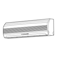
Detailed diagrams and dimensions of the indoor unit components and assembly.
Diagrams and dimensions for specific outdoor unit models.
Diagrams and dimensions for specific outdoor unit models.
Wiring diagram for RAS-13UKHP-E4 and RAS-13UAH-E4 models.
Wiring diagram for RAS-10UKHP-E4 and RAS-10UAH-E4 models.
Wiring diagram for RAS-07UKHP-E4 and RAS-07UAH-E4 models.
Wiring diagram for RAS-13UKP-E4 and RAS-13UA-E4 models.
Wiring diagrams for RAS-10UKP/UA-E4 and RAS-07UKP/UA-E4 models.
Wiring diagrams for RAS-13UKPX4/UAX4 and RAS-12UKPX4/UAX4 models.
Wiring diagrams for RAS-10UKPX4/UAX4 and RAS-07UKPX4/UAX4 models.
List and specifications of electrical parts for specific indoor units.
List and specifications of electrical parts for RAS-13UAH-E4 outdoor unit.
List and specifications of electrical parts for RAS-10UAH-E4 outdoor unit.
List and specifications of electrical parts for RAS-07UAH-E4 outdoor unit.
List and specifications of electrical parts for various indoor units.
List and specifications of electrical parts for RAS-13UA-E4 outdoor unit.
List and specifications of electrical parts for RAS-13UAX4/12UAX4 outdoor units.
List and specifications of electrical parts for RAS-10UA-E4/UAX4 outdoor units.
List and specifications of electrical parts for RAS-07UAX4 outdoor unit.
List and specifications of electrical parts for RAS-07UA-E4 outdoor unit.
Refrigeration cycle diagram for RAS-13UKHP/UAH-E4 models.
Refrigeration cycle diagram for RAS-10UKHP/UAH-E4 models.
Refrigeration cycle diagram for RAS-07UKHP/UAH-E4 models.
Refrigeration cycle diagrams for various RAS-13/12 UKP/UAX4 models.
Refrigeration cycle diagrams for various RAS-10 UKP/UAX4 models.
Refrigeration cycle diagrams for various RAS-07 UKP/UAX4 models.
Control block diagram for specific HP models.
Control block diagram for various UKP/UAX4 models.
General overview of air conditioner control logic and components.
Details the control circuits for different operation modes.
Describes the operation when the Hi POWER mode is activated.
Controls heat exchanger temp. to prevent refrigerating cycle pressure issues.
Detects indoor heat exchanger temp. to prevent freezing.
Describes melting ice from outdoor heat exchanger during heating operation.
Manages outdoor fan control to prevent input current exceeding specified values.
Enables automatic restart with set conditions after power supply interruption.
Indicates when filters need cleaning after 1000 hours of operation.
Reduces humidity by drying the coil with the internal fan after unit shutdown.
Controls indoor fan speed to maintain low noise levels.
Provides quietness, energy saving, and automatic shutdown for comfort.
Provides critical safety warnings and precautions for installation.
Illustrates the installation steps and component placement for units.
Covers general installation aspects including parts and procedures.
Details on indoor unit installation place, piping, electrical work, and fixing.
Details on outdoor unit installation place, piping, and connections.
Instructions for setting the remote control selector switch for multiple units.
Covers gas leak test, test operation, and auto restart setting.
General steps for troubleshooting air conditioner issues.
Covers essential checks like power supply and cable connections.
Assists in diagnosing problems based on lamp indicators and symptoms.
Guide to using the remote control for self-diagnosis and check codes.
Step-by-step flowcharts for diagnosing common operational faults.
Troubleshooting steps for remote control and indoor P.C. board issues.
Procedure for checking the P.C. board for defects.
Procedures for replacing internal parts of the indoor unit.
Procedures for replacing internal parts of the outdoor unit.
Exploded view and parts list for indoor heat pump models.
Exploded view and parts list for indoor cooling models.
Exploded view and parts list for specific indoor UKHP/UKP-E4 models.
Exploded view and parts list for specific indoor UKPX4 models.
Exploded view and parts list for RAS-13UAH-E4 outdoor unit.
Exploded view and parts list for RAS-10UAH-E4 outdoor unit.
Exploded view and parts list for RAS-13UA-E4 outdoor unit.
Exploded view and parts list for RAS-10UA-E4 outdoor unit.
Exploded view and parts list for RAS-13UAX4/12UAX4 outdoor units.
Exploded view and parts list for RAS-10UAX4 outdoor unit.
Exploded view and parts list for RAS-07UAX4/UA-E4 outdoor units.
Exploded view and parts list for RAS-07UAH-E4 outdoor unit.