– 1 –
FILE NO. SVM-02005(1)
CONTENTS
1. SPECIFICATIONS
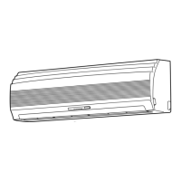
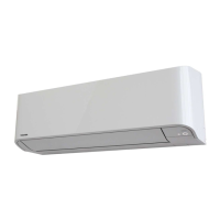
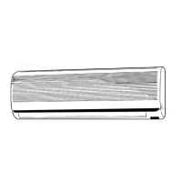
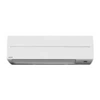
2. CONSTRUCTION VIEWS
2-1 Indoor Unit
2-2 Outdoor Unit (RAS-13UA-ES)
2-3. Outdoor Unit (RAS-10UA-ES)
2-4. Outdoor Unit (RAS-07UA-ES)
3. WIRING DIAGRAM
4. SPECIFICATION OF ELECTRICAL PARTS
4-1 Indoor Unit
4-2 Outdoor Unit (RAS-13UA-ES)
4-3 Outdoor Unit (RAS-10UA-ES, RAS-07UA-ES)
5. REFRIGERATION CYCLE DIAGRAM
5-1 RAS-13UKP-ES / RAS-13UA-ES
5-2 RAS-10UKP-ES / RAS-10UA-ES
5-3 RAS-07UKP-ES / RAS-07UA-ES
6. CONTROL BLOCK DIAGRAM
7. OPERATION DESCRIPTION
7-1 Outline of Air Conditioner Control
7-2 Description of Operation Circuit
7-3 Hi POWER Mode
7-4 High-Temperature Limit Control
7-5 Low-Temperature Limit Control
7-6 Auto Restart Function
7-7 Filter Check Lamp
8. INSTALLATION PROCEDURE
8-1 Safety Cautions
8-2 Installation Diagram of Indoor and Outdoor Units
8-3 Installation
8-4 Indoor Unit
8-5 Outdoor Unit
8-6 How to Set Remote Control Selector Switch
8-7 Others
9. TROUBLESHOOTING CHART
9-1 Troubleshooting Procedure
9-2 Basic Check Items
9-3 Primary Judgement
9-4 Self-Diagnosis by Remote Control (Check Code)
9-5 Troubleshooting Flowcharts
9-6 Troubleshooting for Remote Control (Including The Indoor P.C. Board)

 Loading...