Do you have a question about the Toshiba RAS-10NKHD-E and is the answer not in the manual?
| Cooling Capacity | 2.5 kW |
|---|---|
| Heating Capacity | 3.2 kW |
| Refrigerant | R410A |
| Power Supply | 220-240V, 50Hz |
| Energy Efficiency Ratio (EER) | 3.21 |
| Coefficient of Performance (COP) | 3.61 |
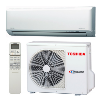
| Type | Split System Air Conditioner |
Details of the indoor unit's physical structure and dimensions.
Details of the outdoor unit's physical structure and dimensions for specific models.
Details of the outdoor unit's physical structure and dimensions for specific models.
Wiring diagram for the RAS-13NKHD-E/RAS-13UAH-E3 model.
Wiring diagram for RAS-10NKHD-E/RAS-10UAH-E3 and RAS-07NKHD-E/RAS-07UAH-E3.
Wiring diagram for the RAS-13NKD-E/RAS-13UA-E3 model.
Wiring diagram for RAS-10NKD-E/RAS-10UA-E3 and RAS-07NKD-E/RAS-07UA-E3.
Electrical parts specifications for indoor units.
Electrical parts specifications for RAS-13UAH-E3 outdoor unit.
Electrical parts specifications for RAS-10UAH-E3 outdoor unit.
Electrical parts specifications for RAS-07UAH-E3 outdoor unit.
Electrical parts specifications for indoor units.
Electrical parts specifications for RAS-13UA-E3 outdoor unit.
Electrical parts specifications for RAS-10UA-E3 outdoor unit.
Electrical parts specifications for RAS-07UA-E3 outdoor unit.
Refrigeration cycle diagram for specific models.
Refrigeration cycle diagram for specific models.
Refrigeration cycle diagram for specific models.
Refrigeration cycle diagram for specific models.
Refrigeration cycle diagram for specific models.
Refrigeration cycle diagram for specific models.
Control block diagram for heat pump models.
Control block diagram for cooling models.
General overview of the air conditioner control system.
Detailed description of the air conditioner's operation circuit.
Explanation of the Hi POWER mode operation.
Control for preventing excessive rise in refrigerating cycle pressure.
Control to prevent the indoor heat exchanger from freezing.
Procedure for defrosting the outdoor heat exchanger in heating mode.
Control to prevent input current from exceeding specified values.
Function for automatic restart after power interruption.
Indication and reset procedure for the filter check lamp.
Function to reduce humidity and prevent mold formation.
Important safety precautions for installation.
Illustrations showing indoor and outdoor unit installation.
General installation guidelines and optional parts.
Details for installing the indoor unit.
Details for installing the outdoor unit.
Steps to follow for troubleshooting.
Fundamental checks before troubleshooting.
Initial diagnosis based on lamp indicators and symptoms.
Using remote control check codes for fault diagnosis.
Flowcharts to diagnose and resolve specific operational issues.
Troubleshooting steps for remote control and indoor unit PCB issues.
Diagnosing issues with the air purifier and minus ion generator.
Procedures for replacing parts of the indoor unit.
Procedures for replacing parts of the outdoor unit.
Exploded view and parts list for the indoor unit's electronic components.
Exploded view and parts list for the indoor unit assembly.
Exploded view and parts list for the RAS-13UAH-E3 outdoor unit.
Exploded view and parts list for the RAS-10UAH-E3 outdoor unit.
Exploded view and parts list for the RAS-13UA-E3 outdoor unit.
Exploded view and parts list for the RAS-10UA-E3 outdoor unit.
Exploded view and parts list for the RAS-07UA-E3 outdoor unit.