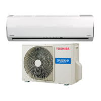
Do you have a question about the Toshiba RAS-10S2AH-E and is the answer not in the manual?
| Type | Split System |
|---|---|
| Cooling Capacity | 2.5 kW |
| Heating Capacity | 3.2 kW |
| Power Supply | 220-240V, 50Hz |
| Refrigerant | R410A |
| Energy Efficiency Ratio (EER) | 3.21 |
| Coefficient of Performance (COP) | 3.61 |
| Indoor Unit Weight | 9 kg |
| Noise Level (Outdoor) | 50 dB(A) |
Specifications for electrical parts used in the indoor units of the specified models.
Specifications for electrical parts used in the outdoor unit of the RAS-10S2AH-E model.
Specifications for electrical parts used in the outdoor unit of the RAS-07S2AH-E model.
Refrigeration cycle diagram for the RAS-10SKHP-E / RAS-10S2AH-E model, including operating conditions.
Refrigeration cycle diagram for the RAS-07SKHP-E / RAS-07S2AH-E model, including operating conditions.
Important safety warnings and precautions for qualified personnel during installation.
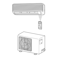
Visual guide showing the placement and connection points for indoor and outdoor unit installation.
Procedures related to the installation process, including parts and arrangements.
Detailed instructions for installing the indoor unit, covering placement, cutting holes, and fixing.
Procedures specific to installing the outdoor unit, including placement, connections, and connections.
Step-by-step diagnostic flowcharts for various operational failures.