Do you have a question about the Toshiba RAS-10SA-E-1 and is the answer not in the manual?
Exploded view and dimensions of the indoor unit.
Exploded view and dimensions of the outdoor unit.
Electrical parts and specifications for the indoor unit.
Electrical parts and specifications for the outdoor unit.
Describes how the unit operates in fan-only mode.
Details the cooling mode operations and controls.
Describes the dehumidification mode and its operation.
Explains the automatic mode selection based on temperature.
Details the energy-saving mode and its effects.
Describes the control to prevent freezing in low temperatures.
Explains how the unit restarts automatically after power failure.
Provides critical safety warnings and precautions for installation.
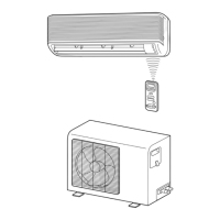
Visual guide showing the placement and mounting of units.
Covers general installation steps and parts.
Specific instructions for installing the indoor unit.
Specific instructions for installing the outdoor unit.
Covers final checks and settings like gas leak test and test operation.
Initial checks to perform before detailed troubleshooting.
Helps identify the likely source of a problem.
Step-by-step diagnostic procedures for specific faults.
Guides on diagnosing issues with the remote control and PC board.
Procedures for replacing parts of the indoor unit.
Steps for replacing the microcomputer.
Procedures for replacing parts of the outdoor unit.
Exploded view and parts list for the indoor unit.
Continuation of exploded view and parts list for the indoor unit.
Exploded view and parts list for the outdoor unit.
| Brand | Toshiba |
|---|---|
| Model | RAS-10SA-E-1 |
| Category | Air Conditioner |
| Language | English |