Do you have a question about the Toshiba RAS-10SAH-E and is the answer not in the manual?
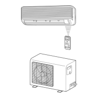
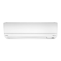
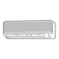
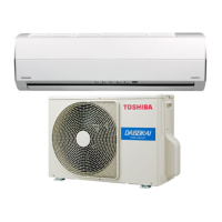
Detailed diagrams and dimensions for the indoor unit components.
Diagrams and dimensions for the outdoor unit components.
Lists electrical components for the indoor unit with part numbers and types.
Lists electrical components for the outdoor unit with part numbers and types.
Lists electrical components for the indoor unit with part numbers and types.
Lists electrical components for the outdoor unit with part numbers and types.
Covers FAN ONLY, COOL, DRY, HEAT, and AUTO modes.
Includes Louver Control, Cool Airflow Control, Temporary Auto, ECONO Mode.
Covers Current Limit, High/Low Temp Limit, and Defrost operations.
Details on setting up and canceling the Auto Restart feature.
Important safety warnings and precautions for installation.
Diagrams showing how to install indoor and outdoor units with dimensions.
Lists optional and kit parts for installation.
Procedures for installing the indoor unit.
Procedures for installing the outdoor unit.
Steps performed after the main installation is complete.
Basic checks to perform before detailed troubleshooting.
Explains operations that might seem like faults but are normal.
Methods for identifying and diagnosing operational problems.
Step-by-step visual guides for resolving specific issues.
Flowchart for diagnosing remote control and indoor P.C. board issues.
Procedures for replacing parts of the indoor unit.
Steps for replacing microcomputer related parts like thermal fuse.
Procedures for replacing parts of the outdoor unit.
Exploded view and parts list for the indoor unit.
Exploded view and parts list for the indoor unit.
Exploded view and parts list for the indoor unit.
Exploded view and parts list for the indoor unit.
Exploded view and parts list for the indoor unit.
Exploded view and parts list for the outdoor unit.
Exploded view and parts list for the outdoor unit.
| Cooling Capacity | 2.5 kW |
|---|---|
| Heating Capacity | 3.2 kW |
| Refrigerant | R410A |
| Power Supply | 220-240V, 50Hz |
| Outdoor Unit Dimensions (HxWxD) | 550x780x290 mm |
| Indoor Unit Weight | 9 kg |
| Type | Air Conditioner |
| Noise Level (Outdoor) | 50 dB |