– 11 –
Standard pressure Surface temp. of heat
P exchanger interchanging Fan speed
50Hz (MPaG) pipe T1 (°C) (indoor)
RAS-10SKH-ES RAS-10SKH-ES
Standard 2,5 40,0 High
Heating High temperature*1 3,1 ~ 3,6 51,0 ~ 58 Low
Low temperature 2,2 36,0 High
Standard 0,9 10,0 High
Cooling High temperature 1,1 16,0 High
Low temperature 0,6 2,0 Low
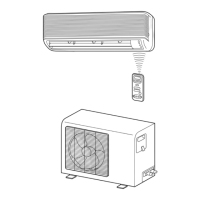
5. REFRIGERANT CYCLE DIAGRAM
RAS-10SKH-ES/RAS-10SAH-ES
Note :
• Measure the heat exchanger temperature at the center of U-bend. (By means of TC sensor.)
*
1 • During heating overload, the high temperature limit control operation is included.
 Loading...