Do you have a question about the Toshiba RAS-10YKH-ES and is the answer not in the manual?
Detailed specifications for various models including capacity, power, and dimensions.
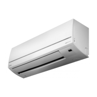
Diagrams and dimensions of the indoor unit for installation and reference.
Diagrams and dimensions of the outdoor unit for installation and reference.
Electrical wiring schematics for the air conditioning unit.
Specifications for electrical components of the indoor unit.
Specifications for electrical components of the outdoor unit.
Diagram illustrating the refrigerant flow for specific models.
Diagram illustrating the refrigerant flow for specific models.
Diagram illustrating the refrigerant flow for specific models.
Diagram illustrating the refrigerant flow for specific models.
Block diagram showing system control logic and components.
Description of the FAN ONLY operating mode.
Description of the COOL operating mode.
How to control the louver position during cooling.
Description of the DRY operating mode.
Description of the HEAT operating mode.
How to control the louver position during heating.
Controls airflow to prevent cool air blow during heating.
Description of the AUTO operating mode.
How to use the Temporary Auto function.
Description of the ECONO. mode.
Control to prevent overcurrent.
Prevents overheating during heating operation.
Prevents freezing during cooling operation.
Controls airflow to prevent cool air blow during heating.
Operation to melt ice on outdoor unit during heating.
Procedure to enable the Auto Restart function.
Procedure to disable the Auto Restart function.
Behavior during timer operations with power failure.
Safety precautions for installation.
Diagrams illustrating indoor and outdoor unit installation.
List of optional and included parts for installation.
Procedures for cutting wall holes and mounting the installation plate.
Procedures for electrical connections and power supply.
Detailed steps for connecting wiring.
Instructions for installing refrigerant pipes and drain hoses.
Detailed steps for physically mounting the indoor unit.
Instructions for proper drainage setup.
Guidelines for selecting an outdoor unit installation location.
List of necessary tools for installation.
Procedures for connecting refrigerant pipes.
Procedure for vacuum pumping the refrigerant system.
Connecting the outdoor unit wiring.
How to perform a gas leak test.
Procedure for performing a test operation.
Information on setting the Auto Restart function.
Initial checks before troubleshooting.
Checking the power supply voltage.
Checking indoor/outdoor unit cable connections.
Understanding normal operation as per programming.
Initial diagnosis of potential issues.
Performing self-diagnosis using the remote control.
Flowcharts for diagnosing problems.
Troubleshooting flowchart for no power.
Troubleshooting after P.C. board replacement.
Troubleshooting flowchart for outdoor unit not operating.
Troubleshooting flowchart for compressor not operating.
Troubleshooting flowchart for outdoor fan not operating.
Troubleshooting for 4-way valve issue.
Troubleshooting flowchart for indoor fan not operating.
Procedure to check remote control and indoor P.C. board.
Precautions and procedures for checking the P.C. board.
Layout diagrams of the P.C. board.
Adjusting the anti-restart timer operation time.
Procedures for replacing indoor unit parts.
Replacement of the microcomputer and thermal fuse.
Procedures for replacing outdoor unit parts.
Exploded view and parts list for indoor unit components.
Exploded view and parts list for indoor unit components.
Exploded view and parts list for outdoor unit components.
| Type | Split System |
|---|---|
| Cooling Capacity | 2.5 kW |
| Heating Capacity | 3.2 kW |
| Power Supply | 220-240V, 50Hz |
| Refrigerant | R32 |
| Energy Efficiency Ratio (EER) | 3.21 |
| Coefficient of Performance (COP) | 3.61 |
| Indoor Unit Dimensions (HxWxD) | 293x798x230 mm |
| Indoor Unit Weight | 9 kg |