Do you have a question about the Toshiba RAS-10YKH-E and is the answer not in the manual?
Details specifications for Indoor Units.
Details specifications for Outdoor Units.
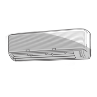
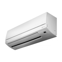
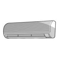
Illustrates the construction and dimensions of the indoor unit.
Illustrates the construction and dimensions of the outdoor unit.
Lists electrical components and their specifications for the indoor unit.
Lists electrical components and their specifications for the outdoor unit.
Describes the operation mode when only the fan is active.
Details the control logic and operation for cooling mode.
Explains the functionality and control during dry mode operation.
Describes the operational procedures and controls for heating mode.
Details how the unit automatically selects modes based on room temperature.
Explains the energy-saving mode and its operation.
Describes how the unit manages current to prevent overload.
Explains controls to prevent overheating in heating operation.
Explains controls to prevent freezing in cooling operation.
Describes airflow control during heating to prevent cool drafts.
Details the process and conditions for defrosting the unit.
Explains the automatic restart feature after power interruptions.
Outlines critical safety warnings and precautions for installation.
Provides visual guidance for the physical installation process.
Covers installation procedures and optional parts.
Details installation steps specific to the indoor unit.
Details installation procedures specific to the outdoor unit.
Covers miscellaneous installation-related tasks like leak tests and operation checks.
Basic checks to perform before detailed troubleshooting.
Methods for initial diagnosis of unit malfunctions.
Flowchart for diagnosing power-on issues.
Troubleshooting specific to post-PC board replacement power issues.
Flowchart for troubleshooting outdoor unit operation failure.
Flowchart for diagnosing compressor-specific issues.
Flowchart for troubleshooting outdoor fan failure.
Flowchart for diagnosing 4-way valve issues.
Flowchart for troubleshooting indoor fan failure.
Procedures for replacing parts of the indoor unit.
Exploded view and parts list for the indoor unit.
Exploded view and parts list for the outdoor unit.
| Brand | Toshiba |
|---|---|
| Model | RAS-10YKH-E |
| Category | Air Conditioner |
| Language | English |