Do you have a question about the Toshiba RAS-137SKV-E and is the answer not in the manual?
Core specification table including electrical, performance, and physical data.
Critical safety advice for handling R410A during installation and servicing.
Guidelines for installing refrigerant piping with R410A, including materials and joints.
List of specialized and general tools necessary for the air conditioner's installation and maintenance.
Details on different types of brazing fillers suitable for copper pipe connections.
Explanation of the necessity and types of flux used in brazing processes.
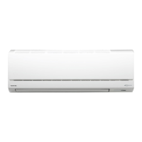
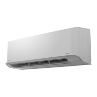
Exploded view and dimensional details of the indoor unit.
Detailed wiring diagram for the RAS-137SKV-E and RAS-137SAV-E models.
Specifications for electrical parts within the indoor unit.
Specifications for electrical parts within the outdoor unit.
Detailed schematic of the refrigerant circuit for specific models.
Control block diagram illustrating the indoor unit's functions and components.
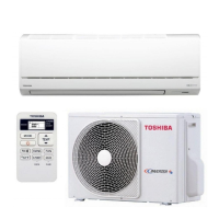
Overview of the air conditioner's control system and the roles of indoor and outdoor units.
Visual guide showing the placement and clearance requirements for unit installation.
Details on parts specifically for the installation process.
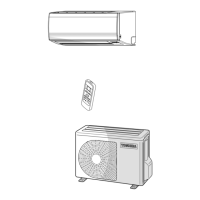
Lists and descriptions of included accessories and installation components.
Guidelines for selecting an appropriate location for the indoor unit installation.
Steps for drilling holes and mounting the indoor unit's installation plate.
Guidelines for selecting an appropriate location for the outdoor unit installation.
Method for checking refrigerant connections for leaks using detector or soapy water.
Steps for conducting a system test to verify proper functionality after installation.
How to enable the auto-restart function after power failure.
Setting the remote controller for operation with one or two indoor units.
Instructions for accessing and operating the remote controller in service and diagnostic modes.
Symptom-based troubleshooting for the indoor unit and remote controller.
Steps to diagnose why the outdoor unit is not operating.
Troubleshooting for cases where the outdoor unit stops shortly after starting.
Summary of diagnostic procedures for the outdoor unit's inverter assembly.
Steps for inspecting and testing the indoor unit's Printed Circuit Board.
Checking procedures for specific indoor unit components like sensors and motors.
Checking procedures for outdoor unit components like compressor, sensors, and valves.
Step-by-step guide for replacing parts within the indoor unit.
Steps for removing major parts of the outdoor unit.
Steps for reassembling the outdoor unit after part replacement.
Instructions for removing and attaching the right and left side cabinets of the outdoor unit.
Steps for removing and replacing the outdoor unit's fan motor.
Procedures for removing and replacing the compressor unit.
Steps for removing and replacing the reactor component.
Procedures for detaching and attaching the electronic expansion valve coil.
Steps for removing and attaching the fan guard.
Procedure for attaching the outdoor heat exchanger temperature sensor.
Procedure for attaching the suction pipe temperature sensor.
Procedure for attaching the discharge pipe temperature sensor.
Procedure for installing the outdoor air temperature sensor.
Exploded view and parts list for the first section of the indoor unit.
| Cooling Capacity | 3.5 kW |
|---|---|
| Heating Capacity | 4.0 kW |
| Power Supply | 220-240V, 50Hz |
| Refrigerant | R410A |
| Indoor Unit Weight | 9 kg |
| Outdoor Unit Dimensions (W x H x D) | 780 x 550 x 290 mm |