Do you have a question about the Toshiba RAS-137SKV-E6 and is the answer not in the manual?
Precautions for general users and installation safety.
High voltage, grounding, and electrical work hazards.
Handling R410A, pressure risks, and safety measures.
Guidelines for copper pipes, joints, and materials.
List of specialized tools for R410A installation and use.
Conventional tools also usable with R410A.
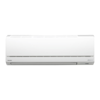
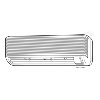
Diagrams detailing the indoor unit's structure and components.
Diagrams detailing the outdoor unit's structure and components.
Schematic showing wiring for indoor and outdoor units.
List and specs of electrical parts in the indoor unit.
List and specs of electrical parts in the outdoor unit.
Diagram illustrating refrigerant flow in cooling/heating.
Operational data linked to temperature conditions.
Block diagram of the indoor unit's control logic.
Block diagram of the outdoor unit's control logic.
General control system and unit roles.
Cooling, Heating, Auto, Dry operation details.
Indoor and outdoor fan speed management.
ECO and Temporary operation functions.
Setting and cancelling auto restart after power loss.
Remote control features, operations, and displays.
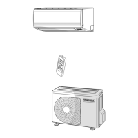
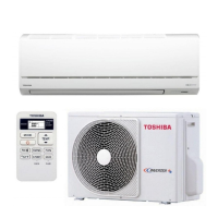
Visual guide for unit placement and mounting.
Lists of accessories, optional parts, and tools.
Site selection, hole cutting, plate mounting, wiring.
Site selection, weather precautions, piping, wiring.
Warnings for high voltage and circuit board handling.
Diagnosing faults via indicator lights and symptoms.
Using the remote for error code diagnostics.
Procedures to check PC boards, sensors, and other parts.
Procedures for replacing indoor unit components.
Procedures for replacing outdoor unit components.
Exploded diagrams and parts lists for the indoor unit.
Exploded diagrams and parts lists for the outdoor unit.
| Type | Split System |
|---|---|
| Cooling Capacity | 3.5 kW |
| Heating Capacity | 4.0 kW |
| Refrigerant | R410A |
| Power Supply | 220-240V, 50Hz |
| Energy Efficiency Ratio (EER) | 3.21 |
| Coefficient of Performance (COP) | 3.61 |
| Noise Level (Outdoor) | 50 dB(A) |