EasyManua.ls Logo

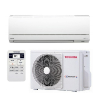
Toshiba RAS-137SKV-E User Manual

Toshiba RAS-137SKV-E
110 pages
To Next Page IconTo Next Page
Page #1 background imageLoading...
Page #1 background image
R410A
SERVICE MANUAL
SPLIT TYPE
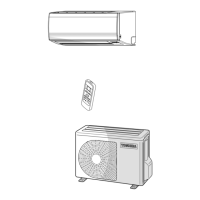
Indoor Unit Outdoor Unit
<High Wall, Heat Pump Type> <Heat Pump Type>
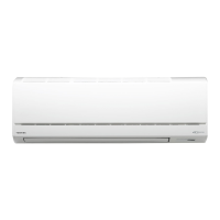
RAS-137SKV-E RAS-137SAV-E
RAS-167SKV-E RAS-167SAV-E
Feb, 2008
FILE NO. SVM-08011

Table of Contents

Question and Answer IconNeed help?

Do you have a question about the Toshiba RAS-137SKV-E and is the answer not in the manual?

Toshiba RAS-137SKV-E Specifications

General IconGeneral
Cooling Capacity3.5 kW
Heating Capacity4.0 kW
Power Supply220-240V, 50Hz
RefrigerantR410A
Indoor Unit Weight9 kg
Outdoor Unit Dimensions (W x H x D)780 x 550 x 290 mm

Summary

Safety Precautions

Air Conditioner Specifications

Detailed Specifications Table

Core specification table including electrical, performance, and physical data.

R410A Refrigerant Safety and Installation

Safety During Installation and Servicing

Critical safety advice for handling R410A during installation and servicing.

Refrigerant Piping Installation

Guidelines for installing refrigerant piping with R410A, including materials and joints.

Installation Tools for R410A Systems

Required Installation and Servicing Tools

List of specialized and general tools necessary for the air conditioner's installation and maintenance.

Pipe Brazing Procedures and Materials

Brazing Materials

Details on different types of brazing fillers suitable for copper pipe connections.

Brazing Flux Usage

Explanation of the necessity and types of flux used in brazing processes.

Air Conditioner Construction Views

Indoor Unit Construction Details

Exploded view and dimensional details of the indoor unit.

Outdoor Unit Construction Details

Air Conditioner Wiring Diagrams

Wiring Diagram for Specific Models

Detailed wiring diagram for the RAS-137SKV-E and RAS-137SAV-E models.

Electrical Parts Specifications

Indoor Unit Electrical Parts

Specifications for electrical parts within the indoor unit.

Outdoor Unit Electrical Parts

Specifications for electrical parts within the outdoor unit.

Refrigerant Cycle Diagram

Refrigerant Cycle Schematic

Detailed schematic of the refrigerant circuit for specific models.

Operation Data Summary

Control Block Diagrams

Indoor Unit Control Block Diagram

Control block diagram illustrating the indoor unit's functions and components.

Outdoor Unit Inverter Assembly Control

Air Conditioner Operation Description

Outline of Air Conditioner Control

Overview of the air conditioner's control system and the roles of indoor and outdoor units.

Detailed Operation Description

Auto Restart Functionality

Remote Controller Functions

Air Conditioner Installation Procedures

Unit Installation Diagram

Visual guide showing the placement and clearance requirements for unit installation.

Optional Parts and Tools

Optional Installation Parts List

Details on parts specifically for the installation process.

Accessory and Installation Parts List

Lists and descriptions of included accessories and installation components.

Installation and Servicing Tools

Indoor Unit Installation Guide

Indoor Unit Installation Location

Guidelines for selecting an appropriate location for the indoor unit installation.

Mounting the Installation Plate

Steps for drilling holes and mounting the indoor unit's installation plate.

Electrical Work and Wiring

Piping and Drain Hose Installation

Indoor Unit Installation Steps

Indoor Unit Drainage Installation

Outdoor Unit Installation Guide

Outdoor Unit Installation Location

Guidelines for selecting an appropriate location for the outdoor unit installation.

Outdoor Unit Drainage and Piping

Refrigerant Piping Connection

Refrigerant System Evacuating Process

Outdoor Unit Wiring Connection

Post-Installation Test Operations

Gas Leak Testing Procedure

Method for checking refrigerant connections for leaks using detector or soapy water.

System Test Operation Steps

Steps for conducting a system test to verify proper functionality after installation.

Auto Restart Function Setup

How to enable the auto-restart function after power failure.

Remote Controller Unit Selection

Setting the remote controller for operation with one or two indoor units.

Air Conditioner Troubleshooting Guide

Initial Troubleshooting Confirmation

Indoor Unit LED Fault Diagnosis

Remote Controller Self-Diagnosis

Service Mode Operation Guide

Instructions for accessing and operating the remote controller in service and diagnostic modes.

Servicing Safety Precautions

Symptom-Based Trouble Diagnosis

Indoor Unit and Remote Controller Symptoms

Symptom-based troubleshooting for the indoor unit and remote controller.

Indoor Fan Motor Operation Faults

Automatic Fan Rotation Troubleshooting

Remote Controller Troubleshooting

Wiring Failure Troubleshooting

Outdoor Unit Non-Operation Diagnosis

Steps to diagnose why the outdoor unit is not operating.

Outdoor Unit Intermittent Stop Diagnosis

Troubleshooting for cases where the outdoor unit stops shortly after starting.

Error Code Diagnosis (1C and 1E)

Outdoor Unit Trouble Diagnosis

Inverter Assembly Diagnosis Summary

Summary of diagnostic procedures for the outdoor unit's inverter assembly.

Main Component Checking

Indoor Unit P.C. Board Inspection

Steps for inspecting and testing the indoor unit's Printed Circuit Board.

Component Check Procedures

Indoor and Outdoor Unit Component Checks

Indoor Unit Other Parts Check

Checking procedures for specific indoor unit components like sensors and motors.

Outdoor Unit Component Checks

Checking procedures for outdoor unit components like compressor, sensors, and valves.

Part Checking Methods

Outdoor Fan Motor Diagnosis

Main Parts Replacement Guide

Indoor Unit Parts Replacement

Step-by-step guide for replacing parts within the indoor unit.

Outdoor Unit Disassembly and Reassembly

Outdoor Unit Part Detachment

Steps for removing major parts of the outdoor unit.

Outdoor Unit Part Attachment

Steps for reassembling the outdoor unit after part replacement.

Outdoor Unit Front Cabinet Replacement

Outdoor Unit Inverter Assembly Replacement

Control Board Assembly Replacement

Outdoor Unit Cabinet and Fan Motor Replacement

Outdoor Unit Side Cabinet Replacement

Instructions for removing and attaching the right and left side cabinets of the outdoor unit.

Outdoor Unit Fan Motor Replacement

Steps for removing and replacing the outdoor unit's fan motor.

Compressor and Reactor Replacement

Compressor Replacement Procedure

Procedures for removing and replacing the compressor unit.

Reactor Component Replacement

Steps for removing and replacing the reactor component.

Expansion Valve Coil and Fan Guard Replacement

Expansion Valve Coil Replacement

Procedures for detaching and attaching the electronic expansion valve coil.

Fan Guard Replacement

Steps for removing and attaching the fan guard.

Sensor Replacement Procedures

TE Sensor Installation

Procedure for attaching the outdoor heat exchanger temperature sensor.

TS Sensor Installation

Procedure for attaching the suction pipe temperature sensor.

TD Sensor Installation

Procedure for attaching the discharge pipe temperature sensor.

TO Sensor Installation

Procedure for installing the outdoor air temperature sensor.

Temperature Sensor Servicing Replacement

Indoor Unit Exploded Views and Parts List

Indoor Unit Component Details (1)

Exploded view and parts list for the first section of the indoor unit.
Indoor Unit Component Details (2)

Outdoor Unit Exploded Views and Parts List

Printed Circuit Board Layouts

Related product manuals