Do you have a question about the Toshiba RAS-13SKVP2-E and is the answer not in the manual?
| Cooling Capacity | 3.5 kW |
|---|---|
| Heating Capacity | 4.0 kW |
| Power Supply | 220-240V, 50Hz |
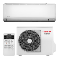
| Outdoor Unit Noise Level | 49 dB(A) |
| Dimensions (Outdoor Unit) | 780 x 550 x 290 mm |
| Outdoor Unit Dimensions (WxHxD) | 780 x 550 x 290 mm |
Critical safety measures for handling R410A refrigerant during installation and servicing.
Guidelines for proper installation of refrigerant piping, including materials and joints.
List of specialized tools necessary for R410A refrigerant system work.
Step-by-step process and safety advice for recharging refrigerant.
Procedures and materials for brazing refrigerant pipes, including flux usage.
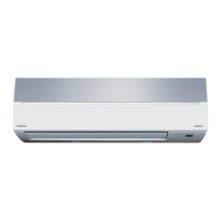
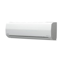
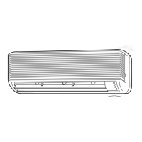
Exploded diagram and key dimensions of the indoor air conditioning unit.
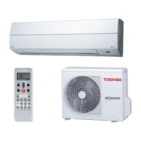
Exploded diagram and key dimensions of the outdoor condensing unit.
Electrical component specifications and ratings for the indoor unit.
Electrical component specifications and ratings for the outdoor unit.
Schematic showing the flow of refrigerant through the system components.
Functional block diagram of the indoor unit's control system and signals.
Functional block diagram of the outdoor unit's control system, including inverter.
General overview of the air conditioner's control system and operation.
Detailed description of various operational modes and functions.
Procedure for setting up and using the auto restart feature after power interruption.
Explanation of the remote controller's buttons, displays, and operational modes.
Visual guide showing the correct placement and connection of indoor and outdoor units.
General installation steps and information on optional installation parts.
Guidelines for selecting the indoor unit's installation location and mounting.
Guidelines for selecting the outdoor unit's installation location and ensuring stability.
Procedures for conducting system tests after installation, including gas leak checks.
Initial checks to confirm power supply and basic operational status.
Methods for initial troubleshooting and identifying the fault category.
Interpreting indoor unit LED fault codes for diagnosis.
Utilizing the remote controller to retrieve error codes and perform self-diagnosis.
Troubleshooting issues based on observed symptoms, including indoor unit and remote controller problems.
Diagnosing specific error codes related to wiring and sensor faults.
General troubleshooting for air purifier and ion generator functions.
Troubleshooting guide for the outdoor unit and inverter assembly.
Methods for checking the functionality of major components like P.C. boards and sensors.
Procedure to diagnose the operational status of the outdoor fan motor.
Step-by-step guide for disassembling and replacing major indoor unit components.
Procedure for replacing the microcomputer assembly.
Procedures for disassembling and reassembling key parts of the outdoor unit.
Exploded view and comprehensive list of parts for the indoor unit.
Exploded view and parts list for the indoor unit's E-parts assembly.
Diagram showing the layout of the P.C. board for the RAS-10SAVP2-E model.
Diagram showing the P.C. board layout for RAS-13SAVP2-E and RAS-16SAVP2-E models.