Do you have a question about the Toshiba RAS-13UA-ES4 and is the answer not in the manual?
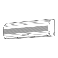
Details of the indoor unit's construction and dimensions.
Construction views and dimensions of specific outdoor unit models.
Construction views and dimensions of the RAS-07UA-ES4 outdoor unit.
Wiring diagram for specific indoor and outdoor unit models.
Wiring diagram for specific indoor and outdoor unit models.
Wiring diagram for specific indoor and outdoor unit models.
List of electrical parts for specified indoor units.
List of electrical parts for specified outdoor units.
List of electrical parts for specified outdoor units.
Refrigeration cycle diagram for specific models.
Refrigeration cycle diagram for specific models.
Refrigeration cycle diagram for specific models.
Control block diagram for specific models.
Control block diagram for specified models.
Overview of the air conditioner control system.
Explanation of the operation circuit and control logic.
How the unit operates in Fan only mode.
How the unit operates in Cooling mode.
How the unit operates in Dry mode.
Heating operation details for heat pump models.
High power mode for enhanced cooling/heating.
Prevents excessive pressure increase by limiting indoor heat exchanger temp.
Prevents indoor heat exchanger freezing by limiting low temp.
Operation to melt ice from outdoor heat exchanger during heating.
Automatically restarts the unit after power interruption.
Important safety warnings and precautions for installation.
Visual guide for installing indoor and outdoor units.
List of optional parts for installation.
List of included accessories and installation parts.
Tools required for installation and servicing of R410A systems.
Recommended locations for installing the indoor unit.
Steps for preparing the wall and mounting the installation plate.
Instructions for electrical connections and power supply.
Steps for installing pipes and drain hoses.
Steps for securely mounting the indoor unit.
Instructions for proper drainage setup for the indoor unit.
Recommended locations for installing the outdoor unit.
Detailed steps for connecting refrigerant pipes.
Procedure for evacuating air from the refrigerant system.
Connecting the electrical wiring between units.
Setting the selector switch using the remote control.
Procedures to check for refrigerant gas leaks.
Performing a test run of the unit.
General steps for troubleshooting issues.
Fundamental checks before troubleshooting.
Initial assessment of system operation and faults.
Using remote control for fault diagnosis via check codes.
Step-by-step troubleshooting guides for common problems.
Diagnosing remote control and indoor P.C. board issues.
Procedures for replacing parts of the indoor unit.
Procedures for replacing parts of the outdoor unit.
Exploded view and parts list for indoor unit heat pump models.
Exploded view and parts list for indoor unit cooling models.
Exploded view and parts list for the indoor unit.
Exploded view and parts list for outdoor unit model RAS-13UAH-ES4.
| Cooling Capacity | 3.5 kW |
|---|---|
| Heating Capacity | 4.0 kW |
| Refrigerant | R32 |
| Power Supply | 220-240V, 50Hz |
| Coefficient of Performance (COP) | 4.0 |
| Model | RAS-13UA-ES4 |
| Type | Air Conditioner |
| Noise Level (Indoor) | 19 dB(A) |
| Outdoor Unit Dimensions (WxHxD) | 780 x 550 x 290 mm |