EasyManua.ls Logo

Toshiba RAS-13UAH-ES4 User Manual

Toshiba RAS-13UAH-ES4
84 pages
To Next Page IconTo Next Page
Page #1 background imageLoading...
Page #1 background image
FILE NO. SVM-05020
SERVICE MANUAL
AIR CONDITIONER
SPLIT WALL TYPE
RAS-13UKHP-ES4 / RAS-13UAH-ES4
RAS-10UKHP-ES4 / RAS-10UAH-ES4
RAS-13UKP-ES4 / RAS-13UA-ES4
RAS-10UKP-ES4 / RAS-10UA-ES4
RAS-07UKP-ES4 / RAS-07UA-ES4
May 2005

Table of Contents

Question and Answer IconNeed help?

Do you have a question about the Toshiba RAS-13UAH-ES4 and is the answer not in the manual?

Toshiba RAS-13UAH-ES4 Specifications

General IconGeneral
TechnologyInverter
Cooling Capacity3.5 kW
Heating Capacity4.0 kW
Energy Class CoolingA
Energy Class HeatingA
Power Supply220-240V, 50Hz
Weight (Indoor Unit)9 kg
TypeSplit
Outdoor Unit Dimensions (W x H x D)780 x 540 x 285 mm

Summary

Air Conditioner Specifications

Unit Construction Views

Indoor Unit Construction

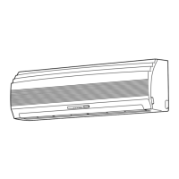
Visual representation and dimensions of the indoor unit.

Outdoor Unit Construction (10 & 13 Series)

Diagrams and dimensions for specific outdoor unit models.

Outdoor Unit Construction (07 Series)

Diagrams and dimensions for the 07 Series outdoor unit.

Wiring Diagrams

Wiring Diagram (10UKHP/10UAH)

Electrical schematic for specific indoor/outdoor unit combinations.

Wiring Diagram (13UKP/13UA)

Electrical schematic for specific indoor/outdoor unit combinations.

Wiring Diagram (07UKP/07UA)

Electrical schematic for specific indoor/outdoor unit combinations.

Electrical Parts Specifications

Indoor Unit Electrical Parts

List and specs of electrical components for indoor units.

Outdoor Unit Electrical Parts (10/13 Series)

List and specs of electrical components for outdoor units.

Outdoor Unit Electrical Parts (07 Series)

List and specs of electrical components for specific outdoor units.

Refrigeration Cycle Diagrams

Refrigeration Cycle (13UKHP/13UAH)

Schematic of the refrigerant cycle for specific models.

Refrigeration Cycle (10UKHP/10UAH)

Schematic of the refrigerant cycle for specific models.

Refrigeration Cycle (13UKP/13UA)

Schematic of the refrigerant cycle for specific models.

Control Block Diagrams

Control Diagram (10/13UKHP/UAH)

Block diagram of the control system for specific models.

Control Diagram (07/10/13UKP/UA)

Block diagram of the control system for specific models.

Operation Description

Air Conditioner Control Overview

General description of the control system and its components.

Operation Circuit Descriptions

Detailed explanation of various operation modes and circuits.

Hi POWER Mode Operation

Explanation of the Hi POWER operating mode.

Defrost Operation

Procedure and conditions for defrost operation in heating mode.

Current Limit Control

Auto Restart Function

Filter Check Lamp Function

Self-Cleaning Function

Quiet and Comfort Sleep Modes

Installation Procedures

General Safety Cautions

Important safety instructions for installation and handling.

Unit Installation Diagrams

Visual guide for positioning and installing indoor and outdoor units.

Installation Details

Specific steps and considerations for unit installation.

Indoor Unit Installation

Indoor Unit Installation Place

Guidelines for selecting an appropriate location for the indoor unit.

Indoor Unit Mounting Plate Installation

Steps for cutting holes and mounting the installation plate.

Indoor Unit Electrical Wiring

Instructions for performing electrical connections for the indoor unit.

Piping and Drain Hose Installation

Indoor Unit Fixing

Outdoor Unit Installation

Outdoor Unit Installation Place

Guidelines for selecting an appropriate location for the outdoor unit.

Refrigerant Piping Connection

Detailed steps for connecting refrigerant pipes securely.

System Evacuating Procedure

How to remove air and moisture from the refrigerant system.

Outdoor Unit Wiring Connection

Remote Control Selector Switch Setup

Other Installation Procedures

Gas Leak Testing

Procedure for checking refrigerant gas leaks.

Test Operation Procedure

How to perform a test run of the unit.

Troubleshooting Guide

Troubleshooting Procedure Overview

General steps for diagnosing and resolving issues.

Basic Troubleshooting Checks

Initial checks for power supply and connections.

Primary Symptom Judgement

Methods for initial diagnosis based on observed symptoms.

Remote Control Self-Diagnosis

Using Remote Control in Service Mode

Steps to enter service mode for diagnostic checks.

Troubleshooting Flowcharts

Troubleshooting: Unit Won't Turn On

Flowchart for diagnosing power-on issues.

Troubleshooting: Post-PC Board Replacement Power Issue

Flowchart for power issues after replacing the indoor PC board.

Troubleshooting: Outdoor Unit Not Operating

Flowchart for diagnosing outdoor unit operational failures.

Troubleshooting: Compressor Not Operating

Troubleshooting: Outdoor Fan Not Operating

Troubleshooting: 4-Way Valve Failure (Heating)

Troubleshooting: Indoor Fan Not Operating

Part Replacement Procedures

Indoor Unit Component Replacement

Step-by-step guide for replacing indoor unit parts.

Outdoor Unit Component Replacement

Step-by-step guide for replacing outdoor unit parts.

Indoor Unit E-Parts Assy (Heat Pump Model)

Indoor Unit E-Parts Assy (Cooling Model)

Indoor Unit Exploded View

Outdoor Unit Exploded View (13UAH)

Outdoor Unit Exploded View (10UAH)

Outdoor Unit Exploded View (13UA)

Outdoor Unit Exploded View (10UA)

Outdoor Unit Exploded View (07UA)

Related product manuals