– 26 –
Item
2. Indoor fan
motor control
Operation flow and applicable data, etc.
<In cooling operation>
The indoor fan motor is operated in 5 stages in MANUAL
mode (Fig.1) and 5 stages in AUTO mode (Fig. 2)
Table 1 shown the indoor fan speed and air flow rate of
each mode.
Description
* Symbols
UH : Ultra High
H : High
M+ : Medium+
M : Medium
L+ : Low+
L: Low
L- : Low–
UL : Ultra Low
SUL : Super Ultra Low
* The fan speed broadly varies due
to position of the louver, etc.
The described value indicates one
under condition of inclining
downward blowing.
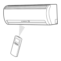
1) When setting the fan speed to L,
L+, M, M+ or H on the remote
controller, the operation is
performed with the constant
speed shown in Fig. 1.
2) When setting the fan speed to
AUTO on the remote controller,
revolution of the fan motor is
controlled to the fan speed level
shown in Fig. 2 and Table 1
according to the setup tempera-
ture, room temperature, and heat
exchanger temperature.
(Fig. 1)
(Fig. 2)
(Table 1) Indoor fan air flow rate
+2.5
Ta
[
˚C
]
+2.0
+1.5
+1.0
+0.5
Tsc
a
b
c
d
e
M+(WB)
*3
*4
*5
L(W6)
Air volume AUTO
L
L+
M
M+
H
W6
(L + M) / 2
W9
(M + H) / 2
WC
Indication
Fan speed
Fan speed setup
COOL ON
AUTO
MANUAL
*3 : Fan speed = [(M +) –L)] x 3/4 + L
*4 : Fan speed = [(M +) –L)] x 2/4 + L
*5 : Fan speed = [(M +) –L)] x 1/4 + L
(Linear approximation
from M+ and L)
Fan speed
level
COOL
DRY
RAS-18N3KCV
Fan speed
(rpm)
Air flow rate
(m3/h)
WF
WE
WD
WC
WB
WA
W9
W8
W7
W6
W5
W4
W3
W2
W1
UH
H
M+
M
L+
L
L-
UL
SUL
UH
H
M+
M
L+
L
L-
UL
SUL
1000
1000
1000
980
920
870
860
800
750
740
700
700
650
500
500
888
888
888
858
795
738
724
658
603
591
547
547
492
325
325
FILE NO. SVM-12053
 Loading...