Do you have a question about the Toshiba RAS-3M23YACV-E and is the answer not in the manual?
Details general specifications, electrical characteristics, and performance data for indoor and outdoor units.
Provides electrical data including voltage, current, power, and fan motor specifications.
Outlines safety precautions and procedures for handling R410A refrigerant during installation and servicing.
Details the types of copper pipes, joints, and processing methods for refrigerant piping installation.
Lists required tools and their interchangeability for R410A refrigerant installation and servicing.
Provides step-by-step instructions for recharging refrigerant in the air conditioner system.
Explains materials for brazing, flux usage, and brazing methods to prevent oxidation.
Illustrates the construction and dimensions of the indoor unit.
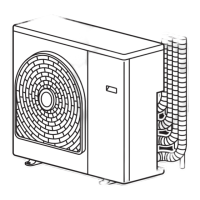
Provides construction details and dimensions for the outdoor unit.
Shows the wiring connections for the indoor unit components.
Details the wiring diagram for the outdoor unit's electrical system.
Lists specifications for electrical parts used in indoor and outdoor units.
Illustrates the refrigerant flow and components within the air conditioner system.
Diagram showing the control functions and connections of the indoor unit's MCU.
Details the control logic and components of the outdoor unit's inverter assembly.
Overview of the air conditioner's capacity control, fan motors, and compressor operation.
Describes Fan Only, Cooling, DRY, Auto, and Temporary operation modes.
Explains the functions and indications of the remote control for operating the unit.
Highlights essential safety precautions for installing the air conditioner unit.
Lists tools required for installation and servicing, noting changes for R410A.
Details the process for installing the indoor unit, including placement and wiring.
Covers installation of the outdoor unit, including piping, electrical work, and testing.
Guides on power supply checks, voltage confirmation, and initial troubleshooting steps.
Explains how to use indoor unit LEDs and remote control for self-diagnosis.
Troubleshooting flowcharts based on symptoms like power issues and motor operation.
Details methods for checking main parts like PC boards, motors, and sensors.
Procedure for replacing internal parts of the indoor unit like front panel, electrical parts, and heat exchanger.
Steps for replacing the microcomputer and related components.
Instructions for disassembling and replacing parts of the outdoor unit, including cabinets and inverter.
Guidance on replacing control boards, rear cabinets, fan motors, compressors, and reactors.
Detailed steps for replacing temperature sensors for servicing.
Diagrams showing exploded views and a list of parts for the indoor unit.
Diagrams showing exploded views and a list of parts for the outdoor unit.
Illustrations of the P.C. board layouts for the main and sub-control units.
| Brand | Toshiba |
|---|---|
| Model | RAS-3M23YACV-E |
| Category | Air Conditioner |
| Language | English |