EasyManua.ls Logo

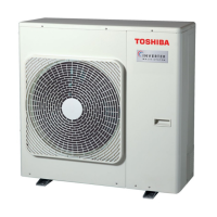
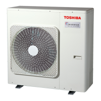
Toshiba RAS-3M26YAV-E User Manual

Toshiba RAS-3M26YAV-E
125 pages
To Next Page IconTo Next Page
Page #1 background imageLoading...
Page #1 background image
SERVICE MANUAL
FILE NO. A01-004
AIR-CONDITIONER
SUPPLEMENT
SPLIT TYPE
PRINTED IN JAPAN, Mar.,2001 ToMo
RAS-M10YKV-E, RAS-M13YKV-E, RAS-M16YKV-E
RAS-4M27YAV-E
RAS-M10YKCV-E, RAS-M13YKCV-E, RAS-M16YKCV-E
RAS-4M27YACV-E
RAS-M10YKV-E, RAS-M13YKV-E, RAS-M16YKV-E
RAS-3M26YAV-E
R410A
• Indoor Unit (1)
• Indoor Unit (2)
• Outdoor Unit
• P.C. board Layout
RAS-4M27YAV-E
RAS-4M27YACV-E
RAS-3M26YAV-E
Parts List
File No. A01-004

Other manuals for Toshiba RAS-3M26YAV-E

Question and Answer IconNeed help?

Do you have a question about the Toshiba RAS-3M26YAV-E and is the answer not in the manual?

Toshiba RAS-3M26YAV-E Specifications

General IconGeneral
BrandToshiba
ModelRAS-3M26YAV-E
CategoryAir Conditioner
LanguageEnglish

Summary

1. SPECIFICATIONS

1-1. Specifications

Detailed specifications for various indoor and outdoor unit models, including capacity, power, noise, dimensions, and piping.

1-3. Electrical Data

Electrical data for outdoor units, detailing system components and power supply requirements.

2. REFRIGERANT R410A

2-1. Safety During Installation/Servicing

Critical safety precautions for handling R410A refrigerant during installation and servicing.

2-2. Refrigerant Piping Installation

Guidelines for installing refrigerant piping, including materials, joints, and processing.

2-4. Recharging of Refrigerant

Step-by-step procedure for recharging the specified amount of refrigerant.

4. WIRING DIAGRAM

8. OPERATION DESCRIPTION

9. INSTALLATION PROCEDURE

9-1. Safety Cautions

Critical safety precautions for installation, including electrical and refrigerant handling.

10. HOW TO DIAGNOSE THE TROUBLE

10-3. Judgment by Flashing LED of Indoor Unit

Interpreting flashing LED patterns on the indoor unit for self-diagnosis.

10-4. Self-Diagnosis by Remote controller (Check Code)

Using the remote controller to perform self-diagnosis and interpret check codes.

10-5. Judgment of Trouble by Every Symptom

Troubleshooting steps based on specific symptoms, starting with the indoor unit.

10-6. Trouble Diagnosis by Outdoor LED

Interpreting LED indicators on the outdoor unit's sub-control board for self-diagnosis.

10-7. How to Diagnose Trouble in Outdoor Unit

Summarized diagnosis process for the outdoor unit's inverter assembly.

10-9. How to Simply Judge Whether Outdoor Fan Motor is Good or Bad

Procedure to diagnose the outdoor fan motor's status and identify faults.

Related product manuals