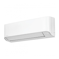
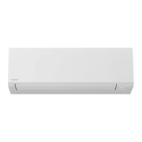
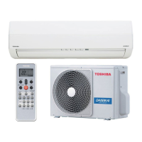
Do you have a question about the Toshiba RAS-B07 and is the answer not in the manual?
Explains hazard symbols and their meanings on the unit.
Covers general cautions, electrical safety, and disconnection procedures.
Emphasizes qualified personnel, safe electrical practices, and proper wiring.
Warns about combustible gases, heat sources, and refrigerant leaks.
Advises against unit modification and specifies installation constraints like weight bearing.
Covers refrigerant types, leaks, pipe thickness, and handling during operation.
General handling advice, moisture, sharp edges, and manufacturer liability.
Covers reporting to power supplier and refrigerant type details.
Lists all included parts for the indoor unit.
Lists all included parts for the outdoor unit.
Illustrates unit placement, piping, and drain hose routing.
Covers fixing bolts, dimensions, and optional installation parts.
Discusses suitable locations for the indoor unit and remote control placement.
Details on cutting holes, mounting the plate, and ensuring secure fixing.
Covers pipe forming, drain hose/cap management, and left-hand connection.
Step-by-step guide on attaching the indoor unit to the installation plate.
Suitable locations for the outdoor unit and drainage considerations.
Specific advice for installing in regions with snowfall and cold temperatures.
Instructions for adding refrigerant and using scales.
Procedures for water-proofing the base plate and installing the drain nipple.
Details on flaring pipes, tightening connections, and torque specifications.
Steps for evacuating air using a vacuum pump and performing an air purge.
Precautions for packed valves and the pump-down process.
Instructions for connecting the cable to the indoor unit terminal block.
Instructions for connecting the cable to the outdoor unit terminal block.
Procedure for installing the air inlet grille on the indoor unit.
Recommended wiring for power supply input at the outdoor unit.
Optional wiring for power supply input at the indoor unit.
Wiring diagram for power input at the outdoor unit terminal block.
Wiring diagram for optional power input at the indoor unit terminal block.
Wiring for power supply input at the outdoor unit terminal block for IMS.
Wiring diagram for the inverter multi system outdoor terminal block.
Covers gas leak test, test operation, and auto restart function setting.
Instructions for A-B selection and applying the B label.
Details work instructions, conditions, and restrictions for reusing existing pipes.
Covers pipe curing, flare nut changes, and machining sizes.
| Type | Split System |
|---|---|
| Cooling Capacity | 2.0 kW |
| Heating Capacity | 2.5 kW |
| Power Supply | 220-240V, 50Hz |
| Refrigerant | R410A |

