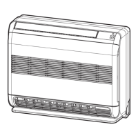
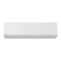
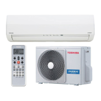
Do you have a question about the Toshiba RAS-B18NKPX and is the answer not in the manual?
Details the wiring diagram for specific 18 Series indoor and outdoor unit models.
Details the wiring diagram for specific 24 Class indoor and outdoor unit models.
Details the wiring diagram for specific 18 Series indoor and outdoor unit models.
Lists specifications for electrical components of the RAS-18NKHP-E indoor unit.
Lists specifications for electrical components of the RAS-18NAH-E outdoor unit.
Lists specifications for electrical components of RAS-24NKP-E/RAS-24NKPX indoor units.
Lists specifications for electrical components of RAS-24NA-E/RAS-24N2AX outdoor units.
Lists specifications for electrical components of RAS-18NA-E/RAS-18N2AX outdoor units.
Illustrates the refrigeration cycle for specific 18 Series models.
Illustrates the refrigeration cycle for specific 24 Series models.
Illustrates the refrigeration cycle for specific 18 Series models.
Illustrates the refrigeration cycle for specific 18 Series models.
Shows the internal control logic and signal flow for the RAS18NKHP-E model.
Shows control logic for multiple models including RAS-18NKP-E and RAS-24NKP-E series.
Explains the basic control logic of the air conditioner.
Details how various operations are controlled.
Details the operation of the unit in cooling mode.
Details the operation of the unit in heating mode.
Explains the unit's automatic mode selection based on temperature.
Explains the high power mode for faster cooling or heating.
Describes the function to restart the unit after a power failure.
Describes the function to reduce coil moisture and prevent mold.
Describes the mode for comfortable sleep with automatic temperature adjustments.
Outlines critical safety precautions for installation personnel and users.
Provides visual guides for installing indoor and outdoor units.
Covers placement, electrical work, piping, and fixing for the indoor unit.
Covers placement, piping, connections, and evacuation for the outdoor unit.
Explains how to configure the remote control selector switch.
Describes methods for checking refrigerant gas leaks.
Guides users through the troubleshooting process.
Covers initial checks and basic failure diagnosis based on indicators.
Explains remote control diagnostics and component fault identification.
Details indoor unit issues and wiring connection problems.
Guides on troubleshooting circuit boards and the remote control.
Procedures for replacing indoor unit components like the front panel and electrical assembly.
Procedures for replacing components in 24 Class outdoor units.
Procedures for replacing components in 18 Class outdoor units.
Exploded view and parts list for the indoor unit's main assembly.
Exploded view and parts list for various indoor unit components.
Exploded view and parts list for 18 Class outdoor units.
Exploded view and parts list for 24 Class outdoor units.
Exploded view and parts list for specific 18 Class outdoor units.
| Brand | Toshiba |
|---|---|
| Model | RAS-B18NKPX |
| Category | Air Conditioner |
| Language | English |


