Do you have a question about the Toshiba RAS-B10N3KV2-E and is the answer not in the manual?
Warnings regarding installation work, R410A, electrical, wiring, gas leakage, and materials.
Safety warnings for qualified persons regarding electrical work and installation.
Table detailing unit capacity, power, noise, dimensions, weight, motor output, and airflow.
Safety precautions for R410A refrigerant installation and servicing.
Procedure for charging refrigerant in liquid form.
Diagram showing the refrigerant flow for cooling/heating.
Diagram showing refrigerant flow for different models.
Overview of the air conditioner's control system and component roles.
Detailed descriptions of basic, cooling/heating, AUTO, and DRY operations.
Operation control flow and functions of remote, indoor, and outdoor units.
Detailed descriptions of Cooling/Heating, AUTO, and DRY operations.
Procedure to set the auto restart function.
Procedure to cancel the auto restart function.
Instructions for ONE-TOUCH, AUTOMATIC, DRY, Hi-POWER, ECO, TEMPORARY, TIMER.
Instructions for PRESET, AUTO RESTART, QUIET, COMFORT SLEEP operations.
Diagrams for installation placement and requirements.
General installation steps and optional parts.
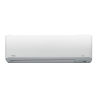
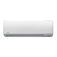
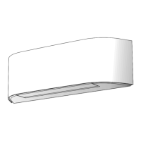
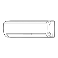
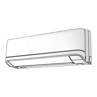
Recommended installation locations and conditions for the indoor unit.
Remote control reception range and placement considerations.
How to connect the connecting cable between indoor and outdoor units.
Instructions for piping and drain hose installation.
Procedures for shaping pipes and connecting auxiliary pipes.
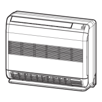
Recommended installation locations and conditions for the outdoor unit.
Flaring and tightening procedures for refrigerant pipes.
Procedure for air purge and evacuation using a vacuum pump.
Requirements for electrical work and power supply.
How to perform a test run operation.
Procedure for cutting holes and mounting the installation plate.
Flaring and tightening procedures for refrigerant pipes.
Instructions for connecting power cord and connecting cable.
Information and procedure for setting the auto restart function.
Table of check codes for diagnosing unit faults.
Flowchart for diagnosing inverter assembly issues.
Procedure for removing and replacing the control board assembly.
| Brand | Toshiba |
|---|---|
| Model | RAS-B10N3KV2-E |
| Category | Air Conditioner |
| Language | English |